Download
1 / 53
540 likes | 638 Vues
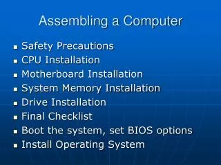
OVERVIEW OF COMPUTER ASSEMBLING. Overview of General Safety Issues. Before beginning any assembly process, review safety procedures. Assembling a computer is not an inherently dangerous job, but being aware of safety procedures is a good starting point.

E N D
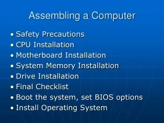
Overview of General Safety Issues • Before beginning any assembly process, review safety procedures. • Assembling a computer is not an inherently dangerous job, but being aware of safety procedures is a good starting point. • In addition to the safety procedures, there are safety concerns with leaving the computer plugged in while working inside it.
ESD Precautions • Electrostatic Discharge (ESD) is more commonly referred to as static electricity. • ESD is probably the greatest problem when a user is unwrapping newly purchased computer parts and components while preparing to assemble the computer. • Just because a discharge cannot be felt does not mean it cannot harm a computer component.
Importance of an Inventory • When building a computer from scratch, it is important to document all of the components and parts that are purchased. • Make sure the specifics about installation and maintenance requirements are saved, so that warranties will be valid.
Desktops • There are two important considerations in choosing a desktop case style for a computer: • Available desktop space • Form factor (describes the general layout of the computer case )
Towers • Tower cases are usually designed to sit vertically on the floor beneath a desk. • Tower cases come in three sizes: • Mid towers • Mini towers • Full-size towers
Power Supplies • The power supply unit provides electrical power for every component inside the system unit. • There are two basic types of power supplies: • AT power supplies • ATX power supplies
Power Supplies • The power supply produces four (five in the ATX) different levels of well-regulated DC voltage for use by the system components. These are +5V, -5V, +12V, and -12V. • In ATX power supplies, the +3.3V level is also produced and is used by the second-generation Intel Pentium processors. The IC devices on the motherboard and adapter cards use the +5V level. • Be able to identify the uses for each voltage level and the corresponding color-coded wire. This will allow testing of the wires using a multimeter to determine if there are problems with the power supply. • The computer power supply produces a voltage only when it has a load.Some component must be running on the machine before a voltage can be found in the power cable connectors.
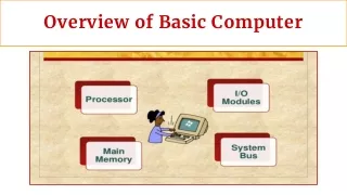
Motherboard Location Map • A motherboard location map shows where the hardware and major components are located on the motherboard. • Typically, everything listed in the specifications section of the motherboard manual is depicted and labeled on the location map. • The main memory is subdivided into slots, and the slots are identified and numbered in sequence DIMM bank 1, DIMM bank 2, and DIMM bank 3.
Motherboard Configuration • Configuring the motherboard typically means the taking the following steps: • Installing the CPU, installing the heat sink and fan, installing RAM, connecting the power supply cables to the motherboard power connectors, connecting miscellaneous connectors to the correct switches and status lights, and setting the system BIOS.
Motherboard Configuration • Location maps allow the correct configuration of the motherboard for the case controls and monitor lights on the front case panel . • For the disk controllers, always remember that a colored stripe on the data cable is pin 1. • The BIOS interface can be keyboard driven, or it can be graphical and mouse driven. • When drives are replaced, memory upgraded, or adapter boards added, the BIOS setup will need to be updated to reflect the configuration changes and saved to the CMOS chip. • The motherboard must be configured for the frequency of the installed processor.
Motherboard Jumpers • A jumper is a pair of prongs that are electrical contact points set into the computer motherboard or an adapter card. • When setting a jumper, place a plug on the prongs that completes or closes the contact. • Closing or opening the circuits establishes logic levels to select functions for the operation of the board.
Motherboard Jumpers • Typically, motherboard jumpers are configured by using a jumper to bridge a pair of pins that are to be connected together (to complete a circuit) on the board. • Removing or inserting jumpers on a set of pins will enable or clear a given option, as specified in the motherboard manual. • There are several additional jumper settings that may have to be set along with the general motherboard configurations: • BIOS Recovery • Clear CMOS • Password Clear • BIOS Setup Access • Processor Voltage
Installing the CPU • Most problems occur when the chip is hastily installed or installed backwards, which causes the chip pins to break. • There are two main types of CPU interfaces. • Socket type • Slot type
Installing the CPU • Most motherboards are flexible enough to handle a variety of CPUs, but most CPUs are very particular about the amount of voltage they can handle. • After installing the CPU, it is important to make sure that the right voltage is present for the proper performance of the processor. • If the proper voltage is not set, total damage to the system could occur, or the whole system will never operate correctly.
Installing the Heat Sink and Fan • Most microprocessors can produce a lot of heat, which if not efficiently dissipated can cause the system to operate intermittently or fail completely. • One way to dissipate heat from processors is to use the heat sink and cooling fan.
Installing RAM • There are two types of memory modules used on most PCs: 168-pin Dual In-line Memory Module (DIMM) cards and 72-pin Single In-line Memory Module (SIMM) cards. • .
Installing RAM • New motherboards do not use SIMMs. It may be found, for example, that the DIMM sockets on the motherboard map are grouped into three or four banks of one slot each. • DIMM1 and DIMM 2 are Bank 0 and Bank 1. • In some cases, motherboards have more than two slots for RAM. These slots would be DIMM3 and DIMM4.
Installing the Motherboard into the Case • Ground yourself properly • Check the manual for the position of the motherboard
Attaching the LEDs, Keylock, and Speaker • LEDs, the status lights, are useful in indicating whether components inside the computer are on or working. • LEDs that could be installed are for power, and the hard drive. • The keylock switch is used to prevent non-authorized individuals from booting the computer and changing the BIOS settings.
Connecting Power Supply Cables to the Motherboard • After successfully installing the motherboard in the computer case, proceed with attaching the appropriate power supply connector(s) to it. • This process is easy with an ATX (boards and power supply) because there is only one connector that is also keyed to fit only one way. • Cover the steps for connecting the power supply cables to the motherboard.
Attaching the Floppy Drive to the Case • The step-by-step process is used for installing either a 3.5” drive or 5.25” drives. • Make sure the floppy cables and power cables are long enough to reach the drive before starting. • Verify the drive is mounted right side up or it will not work.
Floppy Drive Installation Steps • Step 1. Select which drive bay is to be used for the floppy drive. Remove the faceplate of that bay, and save the faceplate for future use. • Step 2. Without connecting anything, insert the drive into the chosen bay, making sure it fits properly. • Step 3. Select the proper size screws (preferably those that came with the drive). If using brackets to hold the drive in place, secure them now, or simply use the screws to attach the drive to the bay.
Floppy Drive Installation Steps • Step 4. Attach the power and ribbon cable to the drive. If other drives are to be installed, this step can be skipped. This provides more maneuvering room in the case, especially if there are no removable drive bays. The drive cable and power cord can then be connected after all the drives have been installed. • Check your work.
Attaching the Hard Drive and CD-ROM to the Case • Attaching the hard drive and CD-ROM are basically similar processes. • Make sure that the interface cable will reach the drive in its intended location. • With IDE/ATA drives, the length of the cable is limited to 18" and less, in some cases. • The designation of a hard drive or CD-ROM drive as either master or slave is generally determined by the jumper configuration, not by the order in which the drive is daisy-chained to the other drive.
Attaching the Hard Drive and CD-ROM to the Case • It is much easier to configure these drives before installing them in the computer case. • Before setting the jumpers, determine the types and number of drives to install. • In a basic system that only has one hard drive, set the jumper to “master”. Some drives have another setting called “single”. • The CD-ROM is similarly easy to configure. However, jumpers may be located in different places on each drive and may even be labeled differently. • Set the CD-ROM to “master” if it is the only drive connected to the second IDE channel.
Attaching the Hard Drive and CD-ROM to the Case • The hard drive can be inserted in any free bay in a computer case. However, there are some things that should be considered: • They can generate a lot of heat. Therefore, keep these drives as far away from other hardware as possible • If it is necessary to install a drive cooler, make sure there is enough room • Install a hard drive away from the power supply • Try to keep the hard drive near the front of the case. It will benefit from the cooling effect of the air current drawn into the case through the front by the system cooling fans
Attaching the Hard Drive and CD-ROM to the Case • Installing the CD-ROM is not very different than installing the hard drive. • Remove the drive bay cover first. Then set the CD-ROM jumper to master since it will be connected to the secondary IDE channel. • Slide the drive into the bay from the front, making sure that it is flush with the front panel, and screw it in place. • In some computer cases, particularly the mini towers, it can be quite challenging to work behind the CD-ROM because of its length and also because it is obstructed by the power supply.
Connecting the Floppy Drive, Hard Drive, CD-ROM, and DVD to the System • The floppy drive exchanges data with the motherboard devices, including the microprocessor, via a 34-pin flat ribbon (data) cable. • The hard drive, CD-ROM, and DVD exchange data signals with the controller on the motherboard by means of a flat ribbon cable. • Cover the four steps to connect the floppy drive to the motherboard. • Cover the four steps to connect the hard drive, CD-ROM, and DVD to the motherboard.
Connecting Power Cables to the Floppy Drive, Hard Drive, and CD-ROM • Small cable drive connectors from the power supply provide power to the floppy, hard drive, and the CD-ROM. The cable connectors have a female 4-pin plug that connects to a male 4-pin connector at the rear of each drive. • Two different power voltages are required for proper functioning of the drives. The circuit board and the logic chips are designed to use the +5v power. The drive motors use the +12v power.
Connecting Power Cables to the Floppy Drive, Hard Drive, and CD-ROM • Attaching the power cables to the floppy drive, hard drive, and the CD-ROM is simple since all the connectors are keyed and can only be inserted one way.
Step-by-Step Installationof the Video Card • The video card as shown is the only expansion card that needs to be installed before booting the PC for the first time. • It is critical in displaying vital information needed to configure the BIOS during the initial boot process. • All the other cards can be installed once the computer is up and running. • Cover the four steps to installing the video card.
Fitting the Case Together • Once all the components and parts have been installed in the case, it is time to complete the PC assembly process. • Check to make sure that all of the pin 1 indicators on the cables match up with all of the pin 1 indicators on the sockets and that connections are snug. • Make sure that all of the screws are properly tightened. • When securing the case, make sure no cables or wires are sticking out or are caught between the parts of the case.
Connecting the Keyboard,Mouse, Monitor, and Power Cord • Connect the basic input and output (I/O) devices that the computer needs to start. These devices can be connected in any order. • Connect the keyboard to the back of the case • Connect the mouse to the back of the computer • Connect the monitor • Plug in the main power supply
What is BIOS? • BIOS stands for Basic Input Output System. • It contains the program code required to control all the basic operating components of the computer system. • BIOS contains the software required to test hardware at boot up, load the operating system, and support the transfer of data between hardware components.
What is BIOS? • The BIOS function runs basic device test programs and then seeks to configure these devices. • The system BIOS and the information required to configure it is stored on a Complementary Metal-Oxide Semiconductor (CMOS) chip. • CMOS is a battery-powered storage chip located on the system board. • The CMOS chip has rewritable memory since the configuration data can be changed or updated as the components or devices in the computer are changed.
Entering the BIOS Configuration • When setting up the computer for the first time, it is necessary to run the CMOS Configuration Setup utility. • Simply pressing the delete key during the opening boot sequence provides access to the BIOS on some computers.
Standard CMOS Setup Screen • Standard CMOS setup screen includes the basic operating parameters that need to be set for the system to work correctly. • These BIOS features are typically universal for all PCs. • The fields available for entering configuration data that are commonly find in this screen are: Date, Time, Hard Disks, Drive A, Drive B, Video, and Halt On.
BIOS Features and Chipset Features Setup Screens • The BIOS Features Setup screen provides advanced features that control the behavior of the system. • This screen is where the system hardware can be fine-tuned for optimal performance. • The Chipset Features Setup screen allows the fine-tuning of the control parameters for the main system chipset.
Password Screens and the Load Setup Defaults Screen • There are two password screens that will be encountered in the BIOS setup: • Supervisor Password • User Password • The Load Setup Defaults screen resets the BIOS setup to default settings.
BIOS Exit Options • There are two BIOS exit options: • Save and Exit Setup • Exit Without Saving Setup • When exiting and saving settings, the computer will restart according to the new configuration.
Startup Sequence • Whenever a computer starts up, a series of tests are automatically performed to check the primary components in the system, such as the CPU, ROM, memory, and motherboard support circuitry. • The routine that carries out this function is referred to as Power-on self-test (POST). • The POST routine provides error or warning messages whenever it encounters a faulty component.