Download
1 / 85
1.02k likes | 1.76k Vues
PIPE INSPECTION AND REPAIR. 2014 CONSTRUCTION ACADEMY Larry Ritchie, FDOT August 7, 2014. PIPE INSPECTION. Over the last 5 years, the Department has spent approximately 175 million dollars on drainage pipe and over 9.5 million dollars on pipe repair.

E N D
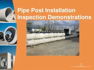
PIPE INSPECTION AND REPAIR 2014 CONSTRUCTION ACADEMY Larry Ritchie, FDOT August 7, 2014
PIPE INSPECTION • Over the last 5 years, the Department has spent approximately 175 million dollars on drainage pipe and over 9.5 million dollars on pipe repair. • With costs like these, it is extremely important to ensure that pipe is installed correctly, inspected thoroughly and replaced or repaired correctly when warranted.
PIPE INSPECTION AND REPAIR The purpose of this presentation is to: • Discuss the Standard Specifications for pipe installation and inspection requirements. • Provide information on the components of a pipe inspection. • Review CPAM Chapter 8.13 guidance on some of the common issues associated with pipe installation. • Review CPAM Chapter 8.13 guidance and the Pipe Repair Matrix for acceptable repair methods.
DRAINAGE INSTALLATION • All work on FDOT projects is governed by the Standard Specifications found in the contract documents. • Drainage installation is covered in at least two separate sections – Section 5 and Section 430 of the Standard Specifications.
DRAINAGE INSTALLATION • Section 5 – Control of Work – describes some of the general guidelines associated with project construction. • Section 5-3 – Conformity of Work with Contract Documents – states the Contractor will “perform all work and furnish all materials in reasonably close conformity with the lines, grades, cross sections, dimensions, and material requirements, including tolerances, as specified in the Contract Documents.”
DRAINAGE INSTALLATION • Section 430 – Pipe Culverts – lists all of the tolerances and construction requirements for furnishing and installing drainage pipe and end sections at locations called for in the plans. • Acceptable pipe materials • Directions for laying pipe • Inspection requirements • Specific requirements for each pipe type
PIPE INSPECTION • FDOT is an optional pipe materials state. We allow the use of both flexible and rigid pipe and have specific performance criteria for each pipe material. • The Department strives for problem-free installation of drainage systems on all FDOT construction projects. • Specifications for installing pipe and the Pipe Inspection Reports are tools used to achieve this goal.
PIPE INSPECTION • Allows the Contractor and the Department to obtain a first hand account of the condition of culvert pipe installed on a construction project. • Provides the Department with some assurance that the Drainage system was installed correctly and is functioning properly.
WHEN TO INSPECT • Section 430-4.8 For pipes installed under the roadway, inspection is to be done when the backfill reaches 3 feet above the pipe crown or upon completion of the stabilized sub-grade. For pipe installed within fills, including embankments confined by walls, inspection is to be conducted when compacted embankment reaches 3 feet above the pipe crown or the finished earthwork grade as specified in the Plans.
WHAT TO DO PRIOR TO INSPECTION • Prior to inspection, dewater the pipe and remove all silt debris and obstructions.
WHAT TO USE • Section 430-4.8 states that for pipe 48 inches or less in diameter, provide the Engineer a video DVD and report using low barrel distortion video equipment with laser profile technology, non-contact video micrometer and associated software.
INSPECTION EQUIPMENT Laser Profiling and Video Inspection Equipment consists of 4 main components: 1. Crawler – moves the equipment through the pipeline. 2. Closed Circuit TV camera – records images and sends data back to a computer. 3. Laser Profiler – provides numerous measurements of a pipe’s internal surface. 4. Software – interprets data and generates an inspection report.
CRAWLER • These machines come with several different wheel sets or tracks that must be changed out to accommodate the size and type of pipe being inspected.
CCTV • The Closed Circuit Television (CCTV) records all of the images for the pipe inspections. This is the equipment that pans and tilts around the inside of a pipe for observations and measurements.
LASER PROFILER • There are currently two different types of technology used for profiling pipe in the Florida. • Rotating head laser profiler • Continuous ring laser profiler
ROTATING PROFILER • The rotating head profiler has two laser diodes built into the CCTV camera head. The diodes take continual measurements while the camera head rotates 360o at a set speed while the crawler is pulled back through the pipe. DIODES
CONTINUOUS RING PROFILER • The continuous ring profiler projects a visible laser beam onto the internal surface of the pipe. The beam is centered in the field of view of the CCTV camera and the camera records the image of the beam as it is pulled back through the pipe.
WHAT NEEDS TO BE INSPECTED ? • For pipe 48 inches or less in diameter, provide the Engineer a video DVD and report using low barrel distortion video equipment with laser profile technology, non-contact video micrometer and associated software that provides: • Actual recorded length and width measurements of all cracks within the pipe. • Actual recorded separation measurement of all pipe joints. • Pipe ovality report • Deflection measurements and graphical diameter analysis report in terms of x and y axis. • Flat analysis report • Representative diameter of the pipe • Pipe deformation measurements, leaks, debris, or other damage or defects. • Deviation in pipe line and grade, joint gaps and joint misalignment.
EVALUATING THE REPORTS • The purpose of generating and collecting pipe inspection information is to compare reports generated by the software with the video observations to determine the presence and extent of defects after installation. • You should not rely on one or the other by itself!
VIDEO INSPECTION • Overall, the quality of the video inspection documentation has improved greatly. However, there are still several areas of concern: • Camera Speed during the video inspection • Partial inspection or completely missing joints • Only inspecting joints and not evaluating the entire pipe
CAMERA SPEED • Move the camera through the pipe at a speed no greater than 30 feet per minute.
JOINT INSPECTION • Film the Entire circumference at each joint.
DOCUMENT DEFECTS • Stop the camera and pan when necessary to document defects.
PIPE OBSERVATIONS • Observation Reports typically include crack and joint gap measurements, sags, joint misalignment and any other type of damage sustained by the pipe. • The defects noted in the report should be compared with the video to verify the location of defects in the pipe run and to ensure no defects were missed during videoing.
PIPE INSPECTION • It is important to remember that the video report is in fact part of the Specifications and can be rejected if they are not performed according to Section 430. • Make sure your pipe inspector is familiar with the language in Section 430-4.8 or he may be performing this service more than once!
RE-INSPECTION • Section 430- 4.8.2 “At any time after reviewing the submitted pipe inspection reports, the Engineer may direct additional inspections. If no defects are observed during the reinspection, the Department will pay for the cost of the reinspections in accordance with 4-3. If defects are observed, the reinspection and all work performed to correct the defects will be done at no cost to the Department. Acceptance of all replacements or repairs will be based on video documentation of the completed work prior to Final Acceptance.”
COMMON PIPE ISSUES SEEN DURING INSPECTION Overall, the majority of pipe issues reviewed and/or repaired have been: • Leaking Joints • Joint Gaps • Deflection • Cracking • Stains
LEAKING JOINTS • Section 430-4.1 Describes the general guideline for laying pipe on FDOT roadway construction projects. • All joints must meet the following minimum standards:
LEAKING JOINTS • Soil tight joints must be water-tight to 2 psi. • Water-tight joints must be water-tight to 5 psi unless a higher pressure rating is required in the plans. • Leaking joints occur in both flexible and rigid pipe types.
LEAKING JOINTS • If joints are leaking, it needs to be determined if the hydrostatic groundwater head exceeds the performance criteria and could cause the joint to leak. • A quick determination can be made using the hydraulic equation: p = wh