Download
1 / 26
260 likes | 422 Vues
12: Electromagnetic Induction. 12.2 Alternating Current. Alternating Current Demo: HEP demo or dynamo Alternating Current and Voltage

E N D
12: Electromagnetic Induction 12.2 Alternating Current
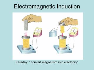
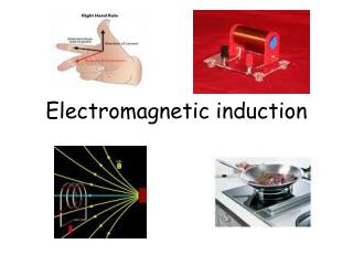
Alternating Current Demo: HEP demo or dynamo Alternating Current and Voltage Whenever a magnet rotates near a coil or wire, its flux will move through the wire or coil inducing an alternating EMF across the coil or wire as a result of Faraday’s Law.
Rotating Coil in a Uniform Magnetic Field A very simple AC generator can consist of a single coil of copper wire being forced to rotate in a uniform magnetic field as shown. At the each end of the wire are connected circular ‘slip rings’. Q1.Explain the design and purpose of the ‘slip rings’ Q2.Why is the coil made from copper wire? Link: AC Generator Applet
This simplified diagram shows a coil ‘end-on’, rotating anti-clockwise: Q3.Explain using Faraday’s Law why the EMF will vary from maximum to zero as angle θ (between the normal to the coil and the field plane) goes from 90° to zero (as shown in the diagrams).
Q4.Plot points on the graph of flux linkage against time (for max positive flux linkage, max negative, zero) and draw the line that goes through them. Considering Faraday’s Law, similarly plot points on the graph of EMF against time and draw the line.
As can be seen from the two graphs, if EMF (ε) is a sinusoidal graph then flux linkage must give a cosine graph. In fact the equations for each are... Nϕ = BAN cosθ(or Nϕ = BAN cosωt) ε = BAN ω sin θ (or ε = BAN ω sin ωt) (You do not need to know these equations however they should make sense to you).
Increasing the speed of rotation • If the coil is rotated at a greater angular speed, the EMF generated will increase and the frequency of rotation will also increase. Hence the graph will change in two ways. • Q5. The graph below shows the output of a coil rotating in a fixed uniform magnetic field. On the same axes, sketch the graph of i. a coil rotating with twice the frequency. • ii. a coil rotating with half the frequency.
Root Mean Square Current In mathematics the Root Mean Square (rms) is a statistical method of determining the magnitude of a quantity that is varying. It can be thought of as a kind of ‘average’ value. In particular it is useful when dealing with sinusoidal variations (that can be positive or negative) such as induced EMF and current from a rotating coil. For discrete values of any quantity the following formula can be applied:
Clearly the calculated value is the square root of the mean of the squares of the discrete values. Q6.Determine the rms value of current from the following graph using eight successive discrete values: I (A)
For electrical output from a coil rotating at constant speed in a uniform magnetic field, the following formulae can be applied: εrms = ε0 √2 Where... ε0= Maximum EMF (V) I0 = Maximum current (A) Irms = I0 √2
Power in AC circuits When calculating the power dissipated in an AC circuit, we use the rms values. Thus, for alternating current circuits... The rms value of an alternating current is identical to the value of direct current that would dissipate power at the same rate through a resistor. Power = Irms x Vrms
Q7. Determine a formula for average power in an alternating circuit in terms of ε0 and I0. • Q8.The rms voltage in Europe is about 230V. • Determine the peak voltage value. • What will be the rms current value through a 20W fluorescent light bulb?
Primary coil Secondary coil Transformers If any two electrical circuits are near to each other, a changing current in one can cause an induced EMF in the other. A transformer uses changing flux linkage produced by one coil to induce an EMF in the second coil.
The input current is a.c. Plot a graph of current in the primary (Ip) against time. The flux in the core is proportional to Ip. Plot a graph of flux in the core against time. The EMF induced in the secondary is proportional to the rate of change of flux linkage. Plot a graph of Induced EMF in the secondary against time.
VsNs VpNp = Transformer Calculations The flux passing through the primary and secondary coils is identical in a 100% efficient transformer. Q.Explain (using Faraday’s Law) why having more turns in the secondary than the primary can lead to the voltage being ‘stepped up’ (increased). The ratio of the turns is equal to the ratio of the voltages:
Ideal Transformers A 100% efficient transformer is known as an ‘ideal transformer’. In this case all the power on the primary side is transferred to the secondary side. Thus... (All values are rms values) IpVp = IsVs
Q.If Np < Ns, which of the following are true (re-write the wrong statements): a. ϕp = ϕs b. flux linkage is equal in both coils c. Ip > Is d. Vp > Vs
Real Transformers • In reality the output power is less than the input power. This could be due to: • Resistance of wires (causing heat transfer) • Eddy currents in core (causing heat transfer) • Flux leakage (not linking into the secondary coil) • Hysteresis (molecular friction) (causing heat transfer) • Q. Suggest a way of decreasing each of the first three losses. • (copper wires; laminated core; improved core design)
Subtitle Text
Subtitle Text
Subtitle Text
Subtitle Text
Subtitle Text
Subtitle Text
Subtitle Text