Download
1 / 58
580 likes | 714 Vues
A DISTRIBUTED FRAMEWORK FOR RELAYING STEREO VISION FOR TELEROBOTICS. M. Al-Mouhamed, O. Toker, A. Iqbal, and M. Nazeeruddin. Contents. Introduction Background Status Of The Problem Literature Review Thesis Objectives Video Client-Server Framework Distributed Telerobotic Framework

E N D
A DISTRIBUTED FRAMEWORK FOR RELAYING STEREO VISION FOR TELEROBOTICS M. Al-Mouhamed, O. Toker, A. Iqbal, and M. Nazeeruddin
Contents • Introduction • Background • Status Of The Problem • Literature Review • Thesis Objectives • Video Client-Server Framework • Distributed Telerobotic Framework • Augmented Reality • Conclusions • Thesis Contributions • Future Research Directions
Introduction • Telerobotics: humans to extend their manipulative skills over a distance, extend eye-hand motion coordination. • Telerobotic applications • Scaled-down: nano-scale, micro-surgery, clean-room • Hazardous: nuclear decommissioning & inspection, fire fighting, disposal of dangerous objects, minefield clearance, operation in harsh environments, unmanned, underwater, ice, desert, space, • Safety: rescue, • Security: surveillance, reconnaissance, • Unmanned: oil platform inspection, repair, • Teaching, training, and entertainment.
Introduction … (cont.) • Minefield clearance, unmanned underwater inspection, and search & rescue. • Those where humans adversely affect the environment such as medical applications and clean-room operations. • Those which are impossible for humans to be situated in such as deep space and nanorobotics.
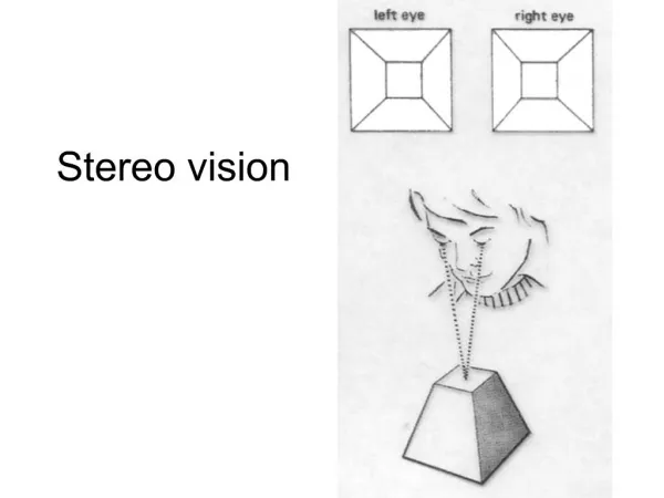
Introduction … (cont.) • Extending eye-hand motion coordination using telerobotics • In natural eye-hand motion coordination, operator sees his hand and react accordingly. • In telerobotics: • Operator holds a master arm to dictate his hand motion, • Motion is transmitted to a remote slave arm and reproduced (replica), • Operator wears a head-mounted display (HMD) to see in 3D the effects of his motion on the remote tool, • Operator does not see his hand (HMD) nor the master arm, his hand is logically mapped to the remote tool, • Operator logically acts on the remote tool seen through the HMD. • Stereo vision: 3D views of slave scene and a metric to calculate 3D positions and orientations of objects.
Background … (cont.) • A two-way logical communication link to transfer commands from client to the server through a Computer Network and to convey LAN • different kinds of feedback, e.g., video, force etc., back to the client site.
Background … (cont.) • A Telepresence system is one which displays high quality information from the remote world, visual or otherwise, in such a natural way that the operator feels physically present at the remote site. • Virtual Reality (VR) is the interactive simulation of a real or imagined environment that can be experienced visually or otherwise in the three dimensions of width, height, and depth.
Video Client-Server Framework • The provision of stereo video on the client side imposes severe requirements in terms of bandwidth to transfer real-time stream of video data in a telerobotic environment. • It requires the use of advanced technologies like DirectX and Windows Sockets to accomplish the capturing and relaying of video data over a LAN. • Commercially available software like Microsoft NetMeeting are optimized for a low band-width network like internet so they show too poor display resolution to be used for stereo vision in a telerobotic setup.
Video Client-Server Framework • Development of a highly optimized client-server framework for grabbing and relaying of a stereo video stream • Server tasks: • Capture or grab stereo images from two cameras • Establish a reliable client-server connection • Upon requests from the client send this stereo frame comprising of two pictures to the client through windows sockets
Video Client-Server Framework • Client tasks: • Detect and establish the connection with server • Establish a highly optimized fast graphic display system to show the pictures received from the server. • Display the pictures arrived from the server and continue in a loop each time asking a new stereo frame from the server. • Allow the viewer to adjust the alignment of pictures on the HMD to compensate for the misalignment and non-linearity present in the camera at server.
Video Client-Server Framework • Proposed client-server framework is based Microsoft Visual C# and Microsoft DirectX. • Microsoft DirectX provides COM based interfaces for various graphics related functionalities. DirectShow is one of these services. DirectShow, further, provides efficient interfaces for the capturing and playback of video data.
Video Client-Server Framework • We can use network services and send/receive data over a network using windows sockets. The stereo video setup uses synchronous windows sockets as an interface between vision server and client. • Two different schemes were implemented to transfer the video data. The schemes differ in the usage of multiple threads on the server side as well as some optimization steps to reduce the network traffic for the transfer of the video data. • A general overview of the image grabbing and displaying system is given before the detailed description of the above scheme.
Video Client-Server Framework • We use a component of DirectShow named SampleGrabber to capture video frames coming through a stream from a stereo camera setup. A block diagram of the scheme used at the server side to grab stereo frames is shown below:
Video Client-Server Framework • In order to show the received pictures from the server, we need to use GDI (Graphics Device Interface). A block diagram of the client side scheme to display the video is shown below:
Video Client-Server Framework(Single Buffer, Serialized Transfer)
Video Client-Server FrameworkDouble Buffer, De-Serialized Transfer • In this scheme, we try to optimize the transfer of video data over the LAN by using thread manipulation on the server. • Thread overlapping among capture and sending thread is achieved using double buffers on the server side. • It is ensured that the thread responsible for sending the video data over the LAN will not wait after receiving a picture request from the client.
Video Client-Server FrameworkDouble Buffer, De-Serialized Transfer
Video Client-Server FrameworkDouble Buffer, De-Serialized Transfer • This approach enables us to send higher number of stereo frames over the same LAN and hardware. • The only overhead is the allocation of extra buffer in the server DRAM which not a real problem with available systems containing large memory.
Video Client-Server Framework3D Visualization • There can be different methods to produce 3D effects on the client side once we have stereo images of the remote scene. • Similarly different hardware device such as eye-shuttering glasses, HMD (Head Mounted Display) are used to show the images to the user. • We have used following two methods for stereo image production on client side: • Sync-Doubling • Page Flipping
Video Client-Server FrameworkSync-Doubling • Left and right eye images are arranged in an up and down way on the computer screen. • A sync-doubler sits between the display output from the PC and the monitor to insert an additional frame v-sync between the left and right frames (i.e. the top and bottom frames). • This will allow the left and right eye images to appear in an interlaced pattern on screen. • Using the frame v-sync as the shutter alternating sync allows us to synchronically transmit the right and left frames to respective left and right eyes, thus creating a three-dimensional image.
Video Client-Server FrameworkPage Flipping • Page-flipping means alternately showing the left and right eye images on the screen. • Combining the 3D shuttering glasses with this type of 3D presentation requires the application of frame v-sync as the shutter alternating sync to create a 3D image. • HMD can also be used in a way that two different images are sent on two different LCD screens of the HMD. The user sees the different image for both eyes thus feeling the depth of the scene. DirectX can be used to flip both the images simultaneously.
Video Client-Server FrameworkPerformance Evaluation • Different experiments were conducted to test the visual quality of the client-server setup as well as find the time delays and other measures of the video data. • The specifications of the stereo frame are as under: • Height of each picture = 288 pixels • Width of each picture = 360 pixels • Size = 304 KB (311040 Bytes) per picture = 608 KB (622080 Bytes) per stereo frame • Each stereo frame is of size 0.6 MB and requires a bandwidth of about 5Mbps/Frame on the LAN. This simple calculation shows the limitation of the 100 Mbps LAN to transfer only 20 fps at the highest possible transfer rate.
Video Client-Server FrameworkPerformance Evaluation • Copying from SampleGrabber to DRAM • Case 1: Copy times on server – Single Force Thread • 300 stereo frames • Mean value = 24.025 ms • 95% CI between 23.29 ms and 24.75 ms.
Video Client-Server FrameworkPerformance Evaluation • Copying from SampleGrabber to DRAM • Case 2: Copy times on server - Two Threads • 300 stereo frames • Mean value = 60.48 ms • 95 CI between 8 ms and 150 ms.
Video Client-Server FrameworkPerformance Evaluation • Copying from SampleGrabber to DRAM • Case 3: Copy times on server with Force transfer over LAN • 300 stereo frames • Mean value = 33.46 ms • 9.43 ms additional for adding network transport thread.
Video Client-Server FrameworkPerformance Evaluation • Transferring over the LAN • Case 1: Single Buffer, Serialized Transfer • 300 stereo frames • Mean value = 86.1 ms • 11.61 stereo frames/second.
Video Client-Server FrameworkPerformance Evaluation • Transferring over the LAN • Case 2: Double Buffer, De-Serialized Transfer • 60,000 stereo frames • Mean value = 58.94 ms • 17 stereo frames/second. • 90% CI between 56.0 and 64.8 ms.
Video Client-Server FrameworkResults Summary • Housheng et. al.[2001] reported a transfer rate of 9-12 fps for a compressed single image of size 200X150 pixels over a LAN. While our scheme transfers 17-18 uncompressed stereo fps of size 360X288 pixels each. • Network bandwidth is near saturated with 18 fps.
A Multi-threaded Distributed Telerobotic Framework • Distributed application programming is one of the different schemes to establish a reliable connection between master and slave arms. • Different items are realized as software components and then these components communicate with each other using distributed components paradigm. • Object Oriented Approach • Software reusability • Easy extensibility • One time debugging • Multi-user environment • Data encapsulation
A Multi-threaded Distributed Telerobotic Framework • By using the distributed programming, network protocol issues can be avoided. The distributed framework itself takes care of all the network resources and binary data transfer over the network. • Previously DCOM (Distributed Component Object Model) based components have been used in telerobotics by Yeuk et. al. • .NET components are more advanced than COM based components and offer complete support of .NET framework including .NET Remoting and SOAP technologies. • Several components are developed on server as well as client side and will be explained briefly.
A Multi-threaded Distributed Telerobotic Framework – MasterArm Component • Local force feedback uses a second order model for minimizing the force applied by the operator. • In order to estimate the force, the component maintains a record of all the force data read for a certain number of samples (history) along with the record of the system time. • Then it evaluates the velocity and acceleration of the master arm at each sampling instant and stores them in a circular buffer. • This information is used to calculate the force proportional to what the operator is applying which is then fed back to the master arm.
A Multi-threaded Distributed Telerobotic System – Performance Evaluation Force and video streams • 3000 force packets. • Mean inter-arrival time = 1.08 ms • An addition of 0.4 ms. • 90% CI between 0.5 and 3.9 ms. • Worst case inter-arrival = 789.74 ms. During the transfer of video data • 3710 force packets. • Mean inter-arrival time = 3.9 ms • 90% CI between 0.5 and 13 ms.
A Multi-threaded Distributed Telerobotic System – Performance Evaluation
A Multi-threaded Distributed Telerobotic System – Performance Evaluation A magnified plot of inter-arrival times in the presence of force, video and command streams.
A Multi-threaded Distributed Telerobotic System – A comparison • Teresa[1999] developed JAVA and VRML based telerobotic system and reported a image acquisition time of 1s for one single frame of 16 bit depth. Our DirectShow based system reports a 24 ms stereo image acquisition time in a telerobotic system. • Al-Harthy[2001] implemented client-server framework takes around 50ms to transfer a command signal (48 bytes) from client to robot. In our case a similar packet (48 bytes) takes from 0.7 to 1.1 ms due to the efficient utilization of raw network resources by .NET Remoting.
Augmented Reality • The basic idea of an AR (augmented reality) reality system is to mix the real and virtual information in order to provide an augmented view of the remote scene that provides more information than a simple video could offer. • AR can be used as an effective way to overcome the effects of time delays in a telerobotic environment. • The information added locally must fit seamlessly into the remote real data so as to avoid any perplexities for the teleoperator.
Augmented Reality – Work Strategy • To introduce non-existent objects to that they appear to be part of the video scene. • Showing a small red ball in the most recent stereo video frame at the position of the gripper calculated locally using the command data from master arm. • Overlaying requires a one-to-one mapping of remote and virtual world coordinate spaces using a camera model. • We use the weak-perspective camera model.
Augmented Reality – Camera Identification • Using a camera model requires the identification of its projection matrix. • Two projection matrices are needed for left and right images for a stereo projection. • A 3D frame of reference serves as affine basis for all other points in the scene. • This affine relationship between frame of reference and other points remains invariant in the projected points.
Augmented Reality – Camera Identification • IdentifyCamera component is designed to help identify both cameras at the system initialization as well as when required. Reference Frame
Augmented Reality – Surfaces, HAL, Page Flipping • Microsoft DirectX is a set of highly optimized application programming interfaces (APIs) for developing high- performance 2D and 3D graphics (or multimedia) applications. • A DirectX surface can be thought of a piece of paper that you can draw on. Provides access to pixels data. • HAL (Hardware Abstraction Layer) provides a common set of graphics functions on all hardware devices. • Primary surface is the current video buffer. We write our next frame data to off-screen secondary surface. In one instruction, graphics device flips the addresses of both surfaces sending the off-screen to output surface -- Page Flipping.
Augmented Reality – Component Framework • On the server side, no new component is added for the AR application. However server side requires setting up cameras, placement and removal of reference frame, etc. • Client side has the following components: • StereoSocketClient component • IdentifyCamera component • RobotModel component • DXInterface component
Augmented Reality – StereoSocketClient Component • A multi-threaded component initialized by client AR application to: • provide necessary un-blocking socket interface to vision server on the remote side by connecting and receiving data through a dedicated thread. • extract single as well as stereo images from binary video data stream being sent from vision server. • synchronize left and right images while providing stereo frames. • Invokes an event when a new stereo frame is received from the server.
Augmented Reality – RobotModel Component • Acts as a passive proxy of PUMA robot on client side. • Provides updated gripper and joint positions in Cartesian space through PUMA direct and inverse geometric models and respectively. • IDecisionServer cannot be used because it is an active proxy of PUMA which does not allow manipulating the position of robot joints independent of PUMA.
Augmented Reality – DXInterface Component • Central component of AR framework. • Runs AR and visualization business in separate threads. • Handles several tasks such as: • Synchronization of real and virtual data • Projection on video surface • Augmentation of real video • Page Flipping for HMD stereo visualization