Download

1 / 62
620 likes | 884 Vues
Demonstration and Information. For further information, please contact:- Dr Amir Rahim The CRISP Consortium Ltd, 164 Cotton Av, London W3 6YG, UK Telephone +(44) (0)771 888 0943 Fax +(44) (0)845 280 2743 E-mail: info@mycrisp.com. Overview Of SAGE CRISP.

E N D
Demonstration and Information For further information, please contact:- Dr Amir Rahim The CRISP Consortium Ltd, 164 Cotton Av, London W3 6YG, UK Telephone +(44) (0)771 888 0943 Fax +(44) (0)845 280 2743 E-mail: info@mycrisp.com
Overview Of SAGE CRISP • SAGE CRISP is a purpose-written Geo-technical, Finite Element Analysis package • CRISP (the FE Analysis engine) has been used successfully by universities and companies for over 20 years • Nearly 100 academic papers have been published using CRISP
Pre-Processor FE Analysis Program Post-Processor Report Generator Help on the GUI Help on FE errors Overview Of SAGE CRISP • SAGE Engineering have added a new user-friendly Graphical User Interface operating under Microsoft Windows 95 and Windows NT. • The SAGE CRISP software suite comprises:
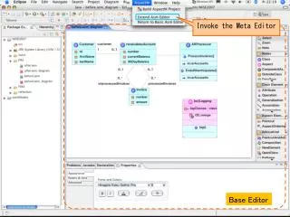
Graphical User Interface • CAD-style, graphical input window allows meshes to be quickly built and altered • Graphical selection of nodes, edges and elements • Full support for WYSIWYG printing and clipboard cut-and-paste operations
Graphical User Interface • Graphically apply displacement fixities to nodes and edges • Graphically apply total or excess pore water pressure fixities to nodes and edges • Graphically apply point or distributed loads to nodes and edges
Graphical User Interface • Graphically add and remove elements to and from the mesh to simulate construction or excavation activity • Graphical representation of each discrete stage of analysis; including the display of loads, fixities and construction sequences • Automatically generate unstructured or structured finite element meshes
Reporting • Report on selected input and output data using the SAGE CRISP Report Generator • Apply formatting to Reports in a standard spreadsheet environment • Store preferred formats as re-usable Templates that can be applied to any Report • Print Reports directly, or export the data for use in other applications
Analysis Types • Drained, Undrained and Fully Coupled (Biot) Consolidation analysis • Two dimensional analysis in Plane Strain or Axisymmetry • Three dimensional analysis (Note: 3D is only available without the graphic pre and post processors)
Constitutive Models • Cam-clay based models including • Original Cam clay (half ellipse) • Modified Cam clay (half circle) • Schofield model with no-tension cutoff limits • Three Surface Kinematic Hardening model
Elasto-plastic Models • Mohr-Coulomb • Drucker-Prager • Tresca • Von Mises • Homogeneous, anisotropic, linear elastic • Non-homogeneous, anisotropic, linear elastic • Elastic-perfectly plastic with the following failure criteria:
Structural elements • Beam, bar and slip (interface) elements
Parametric Analysis • Material Properties • Drainage Conditions • Construction Sequences • Run parametric studies to examine the effect of changing: • Applied Loads • Numerical Dependence • ...and more • Compare results from parametric analyses using the SAGE CRISP Post-Processor
Building a Mesh • Create nodes and elements by drawing them directly onto the screen • Use the Automatic Mesh Generator to quickly and easily build complex finite element meshes from simple super meshes • Unstructured and Structured Automatic Mesh Generators
Unstructured Mesh Generation • Create a freeform Super Mesh containing Super Elements of any shape and with any number of sides • Finite Elements are generated according to grading parameters specified at nodes in the Super Mesh
Structured Mesh Generation • Create a Super Mesh of quadrilateral Super Elements • Finite elements are generated according to the pattern of divisions specified for each edge in the Super Mesh
Boundary Conditions • Fix nodes and edges against horizontal, vertical or rotational movement • Apply prescribed displacements • Drain nodes and edges to either atmosph-eric pressure, or to a static pressure head • Set total or excess pore water pressures • Graphical display of boundary conditions
Define Material Zones • Create ‘Zones’ representing homogeneous regions of soil • Choose constitutive models and define soil parameters for material zones via the Material Properties dialogue box • Coloured display of material zones
Set-up Insitu Conditions • Define in situ conditions in terms of: • Stresses (total or effective) • Pore water pressures (total or excess) • Preconsolidation pressure (for critical state soil models) • Use the Stress Converter to automatically calculate the in situ conditions
Set-up Increment Blocks • An analysis is divided into a number of discrete stages called Increment Blocks • Use Increment Blocks to: • Model each stage of a construction sequence • Apply new or modified boundary conditions • Apply new or modified loads • Allow consolidation to occur • Control numerical accuracy
Example Analysis The following screens are taken from an analysis of the construction of a deep basement close to two tunnels of London Underground’s Central line.
Running An Analysis • The analysis can be run through the Pre-Processor, or directly by command line • Progress messages are issued whilst the analysis is running • Once complete, all analysis output is stored in Microsoft Access database file
Post-Processing • Analysis output can be visualised and reported on in the SAGE CRISP Post-Processor • Post processing features include: • Deformed Mesh Plots • Report Generator • Graphs • Contour Plots • Stress State Plots