Download
1 / 21
210 likes | 310 Vues
Testing OIF Optical and Electrical Implementation Agreements. Gary Goncher Tektronix, Inc. Agenda. OIF Interfaces Mask Testing, Optical and Electrical Jitter Testing Jitter Component Separation Physical Layer Protocol Testing Summary. OIF Interfaces. OIF Electrical Interfaces.

E N D
Testing OIF Optical and Electrical Implementation Agreements Gary Goncher Tektronix, Inc.
Agenda • OIF Interfaces • Mask Testing, Optical and Electrical • Jitter Testing • Jitter Component Separation • Physical Layer Protocol Testing • Summary
OIF Interfaces • OIF Electrical Interfaces
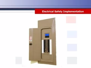
Mask testing • Mask testing measures many parameters simultaneously: • Amplitude (signal to noise) • Rise and fall times • Edge jitter
Mask testing • Example: SFI-5 transmit mask
Jitter Testing • Jitter is mis-positioning of data or clock edges that can result in data bit errors • Jitter results from different causes, and is typically broken into random and non-random (deterministic) components for purposes of bit error estimation • Jitter parameters are specified for all OIF physical interfaces and must be tested
1-sigma or RMS 7-sigma Jitter Testing • Jitter of a random nature has Gaussian distribution
Jitter Testing • Deterministic jitter has non-Gaussian distribution Deterministic components Peak-to-Peak Random components 1-sigma or RMS
Jitter Testing • Measuring Jitter: • Equivalent Time Sampling Methods • Time Interval Analyzer Method • $300,000 BERT Method • Real Time Oscilloscope Method • Separating Jitter: Rj/Dj and BER • ET scope averaging (frame scan) • $170,000 TIA and analysis software • RT scope with analysis software
Jitter Testing • Equivalent time histogram method
rearm T1 T2 T3 T4 start stop start stop Jitter Testing • Time Interval Analyzer Method • T1-T2 then rearm then T1-T3 then rearm… leaving lots of dead time between measurements • No continuous time record means frequency components of jitter can’t be captured • Measurements made over seconds will include wander
Jitter Testing • BERT Method - standard technique to measure BER • Long measurement time (3.25Gbps*1E12*1000=307692s=85hrs) BERT Sig Gen BERT Acquire DUT Trillions of bits: Pseudo-random codes, 1E23 bits common
Jitter Testing • Oscilloscope Rj/Dj Separation and BER Estimation: • Based on real time acquisition data • Includes Golden PLL TIE measurements • Spectral Analysis used to decompose jitter • Wide noise margin – works even with substantial system noise • Works with short or long data repeats – no pattern details required (you provide bit rate and pattern length) • Trigger at any random point in your data • Works with CSA7000, TDS5000, TDS6000, TDS7000 instruments • Results for Rj, Dj, Pj, DDj,
Jitter Component Separation • Start with • TIE • PLL TIE • Perform FFT • Determine frequency and pattern rate • Sum pattern related bins • Sum unrelated periodic bins • Measure RMS of remaining bins • Estimate BER
PLL Protocol Test • Several OIF physical layer interfaces require state machine implementations and pass status messages • Examination of interface state and decode of status messages is necessary for debugging • Examples will be shown for the OIF SPI-4.2 10 Gb/s packet interface
SPI-4.2 Protocol Test • SPI-4.2 Test Requirements • Support SPI-4.2 rates up to 350 MHz clock and 700 Mb/s data rate • SPI-4.2 FIFO Status Decode with DIP 2 parity check • DIP4 Parity Checking for SPI-4.2 data • Trigger on Control (SOP, EOP, ABORT) & Packet Data • Display of Packetized SPI frames • ASCII payload decoding • Per Port Post-processed filtering of data • Real time filtering of IDLE conditions
SPI-4.2 Protocol Test • SPI-4.2 Example – Trigger on MAC • Trigger on Packet (MAC) • Des: 00 00 00 00 00 01 • Src: 00 00 00 00 00 02
FIFO Status Decode Packet Display ASCII payload decoding SPI-4.2 Protocol Test Post-Processing Software • Packet and control word decoding • Packetized display of SPI-4.2 & SPI-3 frames • ASCII payload decoding • Post-processed filtering of data per port (user selectable)
SPI4.2 SOP Trigger Integrated digital/analog probing SPI-4.2 Protocol Test • Integration of physical &protocol information:
Summary • Implementation of physical interfaces requires extensive testing to assure interoperability • Both physical layer electrical/optical properties and protocols must be verified