Download

1 / 19
190 likes | 421 Vues
Microbial Fuel Cells for Sulfide Removal. KORNEEL RABAEY. 1.Introduction 2.Methods Microbial Fuel Cell 구성 Square MFCs 의 실험 Methanogenic UASB 소화조와 Tubular MFC 결합 Tubular MFCs 실험 전기적 Monitoring 과 Data 물질 분석 황 화합물을 산화시키는 Bacteria 의 분리 및 증명 Scanning Electron Microscopy 3.Result

E N D
Microbial Fuel Cells for Sulfide Removal KORNEEL RABAEY
1.Introduction 2.Methods • Microbial Fuel Cell 구성 • Square MFCs의 실험 • Methanogenic UASB 소화조와 Tubular MFC결합 • Tubular MFCs 실험 • 전기적 Monitoring 과 Data • 물질 분석 • 황 화합물을 산화시키는 Bacteria의 분리 및 증명 • Scanning Electron Microscopy 3.Result • Square-Type MFCs의 황 화합물에 의한 전기발생 • Square-Type MFCs의 황 화합물의 산화로 전위 의존 • Tubular Type MFCs 소화조 유출수로 황 화합물 제거 • 연결된 황산염 제거와 Tubular-Type MFCs 아황산 염 구성
Introduction • MFC내 Bacteria는 외부 전기회로(전극)에서 시작하는 전자의 이동.MFCs는 acetate, glucose, wastewater complex과 같은 혼합물의 다양한 변화로 전환할 수 있게 발전됨.MFC reactor Type은 탄소원 화합물의 제거하는데 집중.탄수화물과 황 화합물, 질소화합물을 포함한 혼합기질을 같이 사용하여 MFC에 공급. • 황 화합물은 Fe(Ⅲ)hydroxides처럼 전자 수용체로서 Bacteria로 부터 전자를 쉽게 이동시키는 기능, 다양한 황의 형태로 산화시킬 수 있음.산화 환원 반응 전위와 특징적 반응 조절하여 30여 가지의 다른 형태로 만들 수 있음.
황 화합물은 –0.274V vs SHE보다 더 높은 전위에서 황 원자를 조절하여 산화.더 높은 산화 환원 전위에서 아 황산염과 황산염과 같은 황 이온 형태의 산화반응.Poly Sulfate는 황 원자형태와 황 화합물로 생성 시킬 수 있음. • MFC system은 황 화합물에서 황으로 만들면서 anode의 촉매 산화되는 미생물을 이용처리.Reactor-Type MFCs는 폐수에서 황 화합물과 황산염을 제거하면서 전위 생성. • 협기성 methane 소화조 systems에서 기질로 methane대신 황 화합물을 사용함으로서 황 화합물에서 황산염의 형태로 될 때 처리비용의 감소. • 황 화합물과 황산염이 포함된 물질과 소화조 유출수로 MFC를 사용 ⅰreactor system에서 황 화합물이 산화해서 전기를 생산ⅱMFC system에서 황 화합물의 산화와 분해가 일어날 수 있는지ⅲ이 공정 내에서 어떤 미생물이 연루하는지
Methods • Microbial Fuel Cell 구성 Square-type MFCs (Rabaey et al.): 유입수(sulfide만 포함) 연속식, 회분식으로 유입Anode volume(TAC:320㎖,NAC:170㎖),Granular graphite(1.5~5㎜)사용Cathode volume(TAC:320㎖)1000㎖ 외부 butter vessel를 사용 →cathodic compartment로 반송. Tubular-type MFCs (Rabaey et al.): Anode volume(TAC:390㎖, NAC:210㎖) Granular graphite(1.5~5㎜), Graphite rod(5㎜)채움. Cathode volume(TAC:390㎖,NAC:210㎖)Granular graphite(1.5~5㎜), Graphite felt(5㎜)채움.Membrane 사용. 공기와 접촉 시간에 따른 cathodic 전위의 감소와 이에 수반되는 물질을 알아봄. 실온에서 실험, methane reactors는 35℃로 가온, 전위는 0.197V vs SHE로 계산
Square MFCs의 실험1.황산화물(Na2S xH2O 60~62% 0.1g/ℓ)와 2000㎖외부 buffer vessel로 anode로 재순환anode는 산화된 호기성 황 화합물로 접종시키고 몇 일간 배양50Ω의 외부 저항기는 MFC(reactor A)로 공급 다른 MFC는 open회로 MFC(reactor B)정해진 시간 간격에 따라 미립자가 MFC(reactor A)로부터 제거되었는가를 SEM으로 분석.2.MFC systems에 새로운 다공성 흑연 공급. (위 실험보다 약 10%정도 미립자를 접종) 전위차를 조절하는 mode로 실험. (초기 anode전위를 -0.300V vs SHE로 하고 24시간 동안 최고 0.200V vs SHE 까지 단계적으로 증가)일정한 간격으로 황의 형태를 분석
3.미립자 흑연은 이전의 system으로부터 10%미립자를 다시 공급. 50Ω의 저항기에서 공급, 황 화합물(Na2S xH2O 60~62% 0.1g/ℓ)을 0.720g/ℓ.day 유량에 연속적으로 공급→ 0.6g/ℓ.day NAC, 0.28g/ℓ.dayTAC 황 화합물 공급과 일치.황산화물 공급비는 1.98g/ℓ.day NAC, 0.93g/ℓ.day TAC로 증가됨. • Methanogenic UASB소화조와 Tubular MFC 결합감자 생성공장 UASB Type(내부부피2.5ℓ, 35℃)의 두 협기 소화조에서 sludge채취(pH7, sodium acetate19.3g/ℓ, MgSO47H2O 2.5g/ℓ공급)→MFC유입수( 초기 공급비:4g/ℓday acetate), 1.5m/hr속도 재순환UASB의 유출수를 Tubular-Type MFC로 공급MFC reactor C로 외부 저항기에서 10Ω로 공급조절 reactor는 open회로 (MFC reactor D)황 화합물과 acetate 농도를 MFC 유입전과후에 측정
Tubular MFCs 시험UASB/MFC 로부터 개시된 Tubular MFC에 glucose(1g/ℓ)와 황산염(MgSO47H2O 4.1g/ℓ)가 포함된 폐수를 사용,분리외부 저항기는 초반 100Ω로 유입 (MFC reactor E)3일 후 전위차를 조절하여 실험anodic 전위를 -0.150V vs SHE(2day), -0.100V vs SHE(그 뒤) 조절 reactor는 open 회로(MFC reactor F) • 전기적 Monitoring 과 DataRaboey. et.al 와 Logan. et.al에 따라 수행 분석전위차 측정과 조절은 PAR Bi-Stat Potentiostat사용하여 수행 분석다른 방법으로는 공급과 전기 생산/ NAC unit부피Coulombic 효능은 전극의 기질(COD ㎎/ℓ)이 전기 전환 될 수 있는 능력을 표현 ∈Coulombic = I texp M / F n CODaddedI:전류의 세기 F:Faraday`s의 상수(96485C/mol) texp:실험 시간 CODadded:첨가된 COD양, n:산소 몰이 전기로 전환 되는 수M:산소 몰의 양(32g/mol)
물질 분석GC(FID)로 분석 • 황 화합물을 산화시키는 Bacteria의 분리 및 증명Na2S로서 0.2g/ℓ S2-가 포함된 연속식 Square MFCs에 있는 판에서의 Samples 채취100mM Carbonate buffer로 대체Plate는 27℃ 호기 상태에서 배양. 분자 분석은 Aetermen et. al에 따라 수행.Plate 성장과 분리는 Siller et. Al 따라 수행.질소는 전기 수용원으로 이용하고, Actone은 Na2S(3.9g/ℓ)로 대체 • Scanning Electron Microscopy미립자 흑연 표면을 SEM으로 분석
Result • Square-Type MFCs 황 화합물에 의한 전기 발생반응 장치에 회분식으로 황 화합물을 0.1g/ℓ로 유입anode 전위가 급격하게 감소anode 전위 감소는 cathodic 전해질의 영향에 의해 재생1일 후 황 화합물은 MFC에 의해 제거→이 흐름으로 최대 11㎃ 값을 미침. NAC 37㎽/ℓ, TAC 20㎽/ℓ의 힘 발생에 부합함.황산화물 제거는 전기 회로에 설치된 MFC reactor A에서 완료MFC reactor B의 anodic 전위는 -0.310±0.045V vs SHE→open 회로 전위 0.704±0.049의 결과MFC reactor A 에서 황 산화물에서 황 원자로 전환
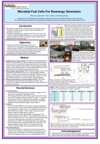
FIGURE 1.Evolution of the redox potential of the anode and the cathode for a sulfide-fed square MFC A (spiked 0.1 g S2- L-1) (potential scalculated vs SHE). Arrows in full indicate the sulfide replenishment; the dashed arrows indicate a cathodic electrolyte replenishment. The decrease of the cathode due to electrochemical losses (step decrease at times 4, 44, and 70 h) and the linear degeneration of thecathodic electrolyte (both directly related to the current density through the MFC) can be discerned on the cathode curves. After 98 h, the hexacyanoferrate-based cathodic electrolyte was replenished without a concomitant sulfide spike.
SEM을 통해 미립자 흑연 표면에 황 원자의 조직을 밝힘(Fig 2a,2b)이 조직은 85% 황과 O, Na, K 15%가 포함(Fig 2c) 이 조직은 8%황과 N. O, P, K, Ca, Na, Fe가 92%가 포함 (Fig 2d)→탄소 함량은 황 보다 낮게 포함 되어 빠짐 • Square-Type MFCs 내 황 화합물의 산화로 전위 의존회분식의 Potentiostatic Test에서 anode 산화 환원반등의 전위는 0.100V/day로 증가 (Fig3.)황을 함유한 액을 MFCs로 재순환-0.300V vs SHE에서 황 화합물이 아닌 물질 산화-0.200V vs SHE에서 황 화합물이 24hr내 산화되어 나타남전위가 점차적으로 증가함에 따라 전류 발생은 낮아짐-0.200V vs SHE의 anode 전위에서 모든 전류 발생은 614±54C로 누적 전환의 전류와 대응, 첨가된 황 화합물은 1929C의 전하에 대응
FIGURE 2. Scanning electron micrographs of white sulfur deposits on the black graphite anode of square-type MFCs fed with sulfide(MFC A): (a) large precipitates on graphite (500); (b) fine grained precipitates (1000); (c) detail of deposit, with sulfur contents up to85% (balance-corrected for carbon); (d) crystallized deposits containing up to 8% sulfur (balance-corrected for carbon).
FIGURE 3. Charge (C) produced by sulfide-fed square-type MFCs as a function of time for a stepwise anode redox potential increase (calculated vs SHE) (times 24, 48, and 72 h). Two reactors were operated simultaneously.
연속식 혼합 유입수에 따른 Square-type MFCs 황 화합물 제거MFCs는 100㎎/ℓ 과 330㎎/ℓ황 화합물 공급(2주 동안 실시)MFCs 유출수의 황 화합물 농도 1.3±1.7㎎/ℓ 과 6.1±7.9㎎/ℓ 로 감소연속식에서 힘의 발생은 NAC에서1.1㎎/ℓ ±0.6㎎/ℓ 과 3.3㎎/ℓ ±6.2㎎/ℓ (최대 3.5㎎/ℓ 와 27.8㎎/ℓ) TAC에서 0.5㎎/ℓ ±0.3㎎/ℓ 과 1.6㎎/ℓ ±2.9㎎/ℓ황 화합물에서 황으로 산화될 때 Coulombic 효율은 29.5%±7.9%~14.6%±4.4%의 공급비→실험 결과 미립자에는 침전된 황의 190㎎±94㎎가 포함 황 화합물이 9±4%에 대응 • Tubular-Type MFCs 소화조 유출수로부터 황 산화물 제거UASB-Type 소화조에 탄소원으로 acetate사용유출수는 MFCs로 유입
Open 회로(MFC reactor C), Close 회로(MFC reactor D)협기성 소화조에서 78%±15%의 acetate가 제거되고3013㎎/ℓ±139㎎/ℓ 유출MFC reactor C를 통하여 acetate 농도가 1391㎎/ℓ ±139㎎/ℓ 로 감소 NAC에서 4769±477㎎/ℓday acetate가 감소TAC에서 2241±224㎎/ℓday acetate가 감소됨으로서 MFC의 힘 산출량은 26±24㎽/ℓ (최대 101 ㎽/ℓNAC, 47 ㎽/ℓTAC)→ 실질적인 힘과 제거가 불안정한 것은 hexacyanoferrate-base cathodic 전해질의 급격한 감소 때문유출수내 황 화합물의 농도는 115±35㎎/ℓ에서 36±49 ㎎/ℓ까지 감소그러므로 278±181㎎/ℓday 최대 278±181 ㎎/ℓday NAC, 131±85 ㎎/ℓday TAC 황 화합물 제거MFC reactor D의 acetate 농도는 558±446 ㎎/ℓ까지 감소 MFC reactor D 의 open회로는 0.721±0.131V, 최대 0.899V였음.
총 제거된 황 화합물은 4396C의 전류와 대응. 총 전하는 system에 의해 36537C정도 전달. →황 화합물 제거에 따른 황산염원자의 전하가 12%정도 황산염의 다른 산화 생성물은(S2O32-, SO32-) 검출되지 않음. 32141C 가까운 물질들은 CH4, CO2의 탄소 화합물과 나머지acetate와 산화되었을 수도 있음. 총 제거된 acetate는 101366C의 전하가 발생(Coulombic 효율) 32%에 가까운 acetate가 산화.
FIGURE 4. Evolution of the anodic and cathodic redox potential (calculated vs SHE) and the produced charge through time for a MFCfed with glucose and sulfate (reactor E). The anodic potential was controlled at -0.150 V vs SHE until 48 h, after which it was increasedto -0.100 V vs SHE.
연결된 Tubular-Type MFCs 황산염과 황의 구성UASB와 Tubular MFCs 연결. 황 화합물과 glucose 공급.Open 회로(MFC F): 황산염 농도(SO42-)533㎎/ℓ→61㎎/ℓ±33㎎/ℓ COD 1060㎎/ℓ→686±327㎎/ℓ까지 감소Close 회로(MFC E): 3일 동안 외부 저항기 100Ω로 공급. 황산염 농도(SO42-)533㎎/ℓ→35㎎/ℓ±29㎎/ℓ COD 1060㎎/ℓ→647±339㎎/ℓ까지 감소anodic 전위는 처음 -150V vs SHE→ -100V vs SHE로 조절.(Fig4.) -100V vs SHE에서 MFC E에서 2±2㎎/ℓ 황 화합물이 제거되는 동안 MFC F에서는 32±17㎎/ℓ 황 화합물이 증가.→ MFC reactor E에서 평균 산출량 anodic 전위가 -150V vs SHE,-100V vs SHE에서 각각NAC 16㎽/ℓ와 36㎽/ℓ, TAC 8㎽/ℓ와 18㎽/ℓ→유입수내 98㎎/ℓ황 화합물이나 NAC내 336㎎/ℓday S2-황 원자 가 제거함 으로서 전하 생성은 1773C