Download
1 / 70
700 likes | 827 Vues
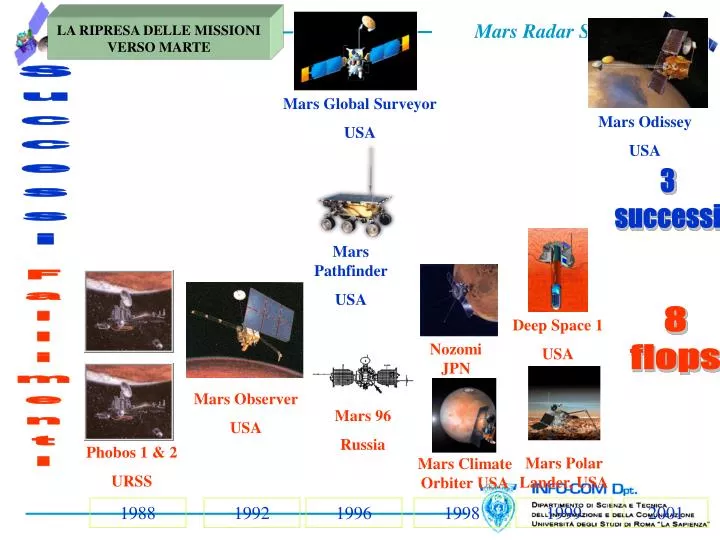
Mars Odissey USA. Mars Global Surveyor USA. Nozomi JPN. Deep Space 1 USA. Mars Pathfinder USA. Mars Polar Lander, USA. Mars Climate Orbiter USA. Mars Observer USA. Mars 96 Russia. Phobos 1 & 2 URSS. LA RIPRESA DELLE MISSIONI VERSO MARTE. Successi. 3 successi. 8 flops.

E N D
Mars Odissey USA Mars Global Surveyor USA Nozomi JPN Deep Space 1 USA Mars Pathfinder USA Mars Polar Lander, USA Mars Climate Orbiter USA Mars Observer USA Mars 96 Russia Phobos 1 & 2 URSS LA RIPRESA DELLE MISSIONI VERSO MARTE Successi 3 successi 8 flops Fallimenti 1988 1992 1996 1998 1999 2001
Vita Strategia di ricerca scientifica • Ricerca dell’ acqua A C Q U A Clima Geologia Quando Dove Forma Quantità Preparazione per l’ esplorazione umana
What is SHARAD? Science Objectives SHARAD is a radar sounder provided by ASI to NASA as a facility instrument, payload of the MRO mission • The primary objective of the SHARAD experiment is to map, in selected locales, dielectric interfaces to a kilometer in depth in the martian subsurface and to interpret these results in terms of the occurrence and distribution of expected materials, including competent rock, regolith, water and ice. • Map the thickness, extent and continuity of the layers within the polar deposits. • Map the thickness, extent and continuity of sedimentary layers. • Map the distribution of shallow buried channels. • Identify regions on Mars for follow-up surface-based water/ice exploration.
MRO Strumenti della missione • Strumenti scientifici HiRISE (High Resolution Imaging Science Experiment) (20m/pixel) CRISM (Compact Reconnaissance Imaging Spectrometer for Mars) (0.4-4) MCS (Mars Climate Sounder)(analisi atmosfera, profilo acqua, sabbia, CO2, temperatura) MARCI (MArs Color Imager)(analisi atmosfera, nubi, ozono, albedo etc. 0.28-0.8) CTX (ConTeXt imager) (6m/pixel) SHARAD (SHAllow (subsurface) RADar). L’ italia è responsabile sia dello studio che della implementazione. • Engineering Payload Electra UHF communication and navigation package Optical navigation camera experiment Ka band telecommunication experiment
Caratteristiche dello S/C • Launch mass: 2180 kg • Size: 14 m solar array tip to tip and 7 m high • Array power: 2 kW in Mars orbit • Maximum data rate: 5.6 Mb/s • 3 m HGA and 100W TWTA • Rolls to +/-30 deg. • 160 Gbit solid state recorder
Apertura dei pannelli solari dopo l’ uscita dall’ atmosfera terrestre
Immagini da Spirit e Opportunity Opportunity 2005 Spirit 2005
Bande di frequenza 1,3-2,3 MHz: 2,5-3,5 MHz; 3,5-4,5 MHz; 4,5-5,5 MHz ~ 70 m (Banda=1 MHz) [150 m nello spazio libero] Risoluzione verticale (εr=5) Da ~ 0,5 Km a ~5 Km Profondità di penetrazione Risoluzione verticale 5-9 Km(along track) x 15-30 Km (across tack) MARSIS I parametri di sistema
MARSIS Le tecniche di riduzione del clutter di superficie Doppler Beam Sharpening: Consiste nel ridurre l’ampiezza del fascio d’antenna sfruttando il moto del satellite per sintetizzare un’antenna di dimensione maggiore di quella reale. In tal modo si riduce l’ampiezza del footprint nella direzione del moto del satellite (along track) con diminuzione degli effetti di riflessione off-nadir. Dual Antenna: Aggiunta di una seconda antenna con un nullo nel diagramma di radiazione in direzione nadir. Ciò consente di valutare le eco off-nadir, che possono essere sottratte da quelle dell’antenna primaria. Dual Frequency Processing: La riflessione superficiale non dipende dalla frequenza, cosa che invece avviene per le riflessioni subsuperficiali. L’utilizzazione di due frequenze e l’elaborazione delle eco relative consente la discriminazione desiderata.
System Parameters (from the SHARAD SFRD) • Centre Frequency: 20 MHz • Pulse Bandwidth: 10 MHz • Radiated Peak Power: 10 W • Pulse Length: 85 us • Antenna Efficiency: > 10% • Pulse Repetition Frequency: 700 Hz, 670Hz, 775 Hz (350, 335, 387.6 Hz) alternate PRF added to cope with orbital extremes during extended phase (including topography margin) • Receive window: 135 us • Receiver gain 80 dB • A/D Resolution: 8 bits • Downloaded sample bits 8 (default), 6, 4 • A/D frequency: 26.67 MHz • Maximum Data Rate: 20.16Mbit/s (@ 700 Hz, no pre-summing) • On-board pre-summing range 1 to 32 samples
DESCRIPTION OF OPERATING GEOMETRY • SHARAD is a nadir looking radar sounder with synthetic aperture capabilities
PRINCIPLES OF OPERATION OF A RADAR SOUNDER 2/3 • In the presence of a dielectric discontinuity in the subsurface, the radar sounder will receive a second echo that is much weaker than the first surface echo. How much weaker this second echo will be depends upon the crust attenuation and the characteristics of the dielectric discontinuity. • If D is the system detection dynamic range, the detection of this second echo will be possible only if its power is no more than D dB less than the first surface signal. • If z is the depth of the interface and f is the frequency of the radar sounder, the instrument will be able to detect this second echo if and only if • The available detection dynamic could be affected by: • Surface Clutter Echoes (coming from off nadir) • Noise • Sidelobes and other artifacts due to the compression of the strong surface echo in presence of phase and amplitude errors Available dynamic Necessary dynamic
SHARAD Sun elevation Magnetic Field Mars Surface 2.3 Planning Tool General Criteria 1/2 Ionosphere fpm SurfaceClutter Sub Surface Material Visible Zone S/N>0 Not Visible Zone S/N<0
HORIZONTAL RESOLUTION (ALONG-TRACK AND CROSS-TRACK) ROUGH SURFACE Limiting the synthetic length at the dimension of DPL in order to avoid RCM problems and more complicated processing, the along-track resolution will be bounded by the DPL dimension as a function of frequency and S/C height. SPECULAR SURFACE the synthetic length is limited by the first Fresnel circle diameter the Raz is a function of S/C height and frequency, The cross-track res. matches the Fresnel diameter
HORIZONTAL RESOLUTION (ALONG-TRACK AND CROSS-TRACK) BOUNDARY CONDITIONS
RANGE (DEPTH) RESOLUTION weighed compressed chirp sidelobes for four different weighting function vs. time and depth of the possible synchronous interface echo depth resolution Vs. the real part of the crust dielectric constant for different weighting function
OBSERVATION GEOMETRY • MRO Orbit Characteristic • periapsis altitude near 255 km; • apoapsis altitude near 320 km; • near-polar inclination of 92.6 degrees; • approximate ground-track repeat cycle of 17 days
Doppler phase evolution • It is possible to denote the following quantities with the following symbols: • R0:Slant range of the observed point • H: Orbital altitude • VR: Radial Velocity of the S/C • VT: Tangential Velocity of the S/C • The evolution of the distance in the synthetic aperture time as a function of the orbit position, including also the surface slope θs, is given is given by:
Doppler phase evolution If monochromatic wave of frequency f and wavelength is transmitted the phase difference between transmitted and received waveform due to the two way travel over range R is given by: Doppler Centroid due to the radial velocity and the tangential velocity component due to surface slope Doppler Rate describes the linear frequency modulation induced by the S/C tangential motion Variable with λ: high fractional bandwidth should be considered
AZIMUTH PROCESSING FOR A LOW FREQUENCY WIDE BAND RADAR: FOCUSED PROCESSING • Doppler rate compensation has to be done adaptively in the frequency • If it is done only on the carrier the resulting azimuth compressed pulse is the following
AZIMUTH PROCESSING FOR A LOW FREQUENCY WIDE BAND RADAR: FOCUSED PROCESSING • The same result could have been obtained considering again the maximum mismatching in the Doppler rate (as for Cook and Bernfeld chap 6) The doppler rate correction has to be performed adaptively in the frequency with a step of at least 1Mhz.