Download
1 / 44
440 likes | 537 Vues
Instrumentation Session. 10:30am - Session: BigBOSS Instrumentation I Speakers: Mike Sholl - Telescope + Optics + Requirements Eric Prieto – Spectrograph Stephan Aune - Cryogenic design 12:00pm - Lunch 1:00pm - Josh Bloom - Transient Follow-up, SASIR survey

E N D
Instrumentation Session • 10:30am - Session: BigBOSS Instrumentation I Speakers: • Mike Sholl - Telescope + Optics + Requirements • Eric Prieto – Spectrograph • Stephan Aune - Cryogenic design • 12:00pm - Lunch • 1:00pm - Josh Bloom - Transient Follow-up, SASIR survey • 1:30pm - Session: BigBOSS Instrumentation II Speakers: • Mike Sholl – Prime focus options (for Ming Liang), actuators, fiber camera • Charlie Baltay - Fiber view camera • Chao Zhai (USTC) - Fiber Positioners • 2:30pm - Break • 3:00pm - Session: BigBOSS Instrumentation III Speakers: • Chris Bebek - Detectors CCD • Mike Schubnell - Detectors NIR • Natalie Roe - BOSS spectrographs
Telescope Optics & RequirementsPresented to: BigBoss Collaboration Meeting M. Sholl University of California at Berkeley Space Sciences Laboratory & Lawrence Berkeley National Laboratory 20 November 2009
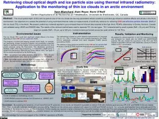
Growth of Large Scale StructureThree Observational Techniques of JDEM Baryon Acoustic Oscillation Supernovae Weak Lensing Eisenstein et al, astro-ph/0501171 Jain, Seljak, White Density waves in the matter of the early universe, visible today BAO correlation length provides a “standard ruler” revealing just how much linear cosmic expansion has occurred at each redshift. ~100Mpc autocorrelation length scale Type Ia SNe, no H or He, strong Si: standard candle Flux ~luminosity/distance2 lookback time Redshift universe’s scale at lookback time Foreground matter concentrations distort background galaxy shapes Mass aggregation w.r.t. redshift is determined by expansion history Mapping lensing vs. redshift constransn expansion models
Survey Goals and Challenges of JDEM Baryon Acoustic Oscillation Supernova Weak Lensing Eisenstein et al, astro-ph/0501171 Jain, Seljak, White ~ 200 x 106 emission line galaxies Redshift accurate to ~ 0.1% for each galaxy ~ 20,000 deg survey to z=2 Challenges: Collimated exit pupil preferred for prism spectroscopy 2x more coarse pixel scale compared to SNe and WL Discover 750-1500 SNe over several years 5-day revisit cadence VIS-NIR (0.38-2.0μm) 10 square-degree-years Challenges: Calibration of band-to-band photometric errors at the ~1% level (covered in numerous previous papers) Detect ~ 1% distortion by foreground matter >109 galaxies >10000 square degrees 0.1 to 0.2 arcseconds Nyquist sampled pixel scale for shape determination Challenges: PSF stability to 0.1%
Why go to Space? (Lampton) • Issues that dominate survey rate & photometric accuracy • Atmospheric transmission vs. wavelength (& stability!) • Atmospheric emission vs wavelength (& stability!) • Atmospheric seeing (& stability!) • Space • SkyBrightness = AlderingZodi(λ) + 0.08·BBody(λ) • Aeff = Atelescope . QE, • Ωpho(λ) = Ωgalaxy(z) + ΩAiryDisk(λ) + Ωpixel • Ground • Sky = AlderingZodi(λ) + Atmospheric emission(λ) + 0.08·BBody(λ) • Aeff = Atelescope · QE ·Tatmos • Ωpho(λ) = Ωgalaxy(z) + Ωseeing(λ) + ΩAiryDisk(λ) + Ωpixel
Ground Based: Atmospheric Transmissionhttp://www.gemini.edu/sciops/ObsProcess/obsConstraints/ocTransSpectra.html J band H band K band 1.6 mm H2O at Gemini North
Ground Based: Atmospheric Emissionhttp://www.gemini.edu/sciops/ObsProcess/obsConstraints/ocSkyBackground.html Sky brightness at visible wavelengths: not too horrible (linear scale) Sky brightness at NIR wavelengths: horrible (note log scale)
Proposed Space-Based Dark Energy Missions ADEPT CIP DUNE DESTINY EUCLID JEDI SNAP SPACE JDEM
Why not Space? …Rocket EquationSource: Thompson, Intro to Space Dynamics
Why not Space? …Rocket EquationSource: Thompson, Intro to Space Dynamics Conservation of Momentum Conservation of mass
Why not Space? …Rocket EquationSource: Thompson, Intro to Space Dynamics Conservation of Momentum Conservation of mass
Why not Space? …Rocket EquationSource: Thompson, Intro to Space Dynamics Conservation of Momentum Conservation of mass Burnout Velocity Burnout Time
Rocket Equation • T/W0 is a measure of liftoff acceleration (measured in g’s), and the necessary structural capability of the booster. (High T/W0 helps) • Rm is the mass ratio of fuel to structure (including tanks, motors and payload) • In order to achieve orbit, one needs a vbo of 7.6 kilometers/s. • SSTO is impractical • Staging is necessary • Achieving Earth orbit will be expensive until high-thrust motors with high Ispare developed
Does Breathing Air Help? • Ref. John C. Whitehead, LLNL, AIAA 2007-5837
Does Breathing Air Help? • Ref. John C. Whitehead, Lawrence Livermore National Lab • No! Atmospheric oxygen is limited • Can you make the inlet bigger?
No! X-43A is mostly inlet, and “only” Mach 10 • Source: Whitehead
Ground Versus Space There are no easy or inexpensive ways to achieve 7.6km/s (Earth orbit) with current state of the art rocket motors Only do an experiment from space if it cannot be done from the ground at reasonable cost, and in a reasonable amount of time
Baryon Acoustic Oscillation can be Done from the Ground!(Numerous talks, 18 November 2009) Baryon Acoustic Oscillation Supernovae Weak Lensing BigBoss Eisenstein et al, astro-ph/0501171 Jain, Seljak, White Density waves in the matter of the early universe, visible today BAO correlation length provides a “standard ruler” revealing just how much linear cosmic expansion has occurred at each redshift. ~100Mpc autocorrelation length scale Type Ia SNe, no H or He, strong Si: standard candle Flux ~luminosity/distance2 lookback time Redshift universe’s scale at lookback time Foreground matter concentrations distort background galaxy shapes Mass aggregation w.r.t. redshift is determined by expansion history Mapping lensing vs. redshift constransn expansion models
Telescope Requirements Overview • FOV: 3º linear • Wavelength Range: • CCD: 340-580nm (Blue), 540-860nm (Green), 820-970nm (Red) • HgCdTe: 0.982-1.130μm (same focal plane in red spectrograph) • Geometric performance: better than 80μm atmospheric seeing, or <~40μm RMS • f/5 (driven by fiber acceptance angle) • Derived for 4m telescope, 20m focal length • Telecentric output to maximize fiber efficiency • Planar focal plane (Cassegrain telescope with corrector) • See Zenxiang Zhou SPIE papers for details of spherical focal plane metrology • Curved focal plane could be accepted with prime focus corrector
Telescope Requirements Overview • Use an existing 4m telescope • Blanco (Chile) • Mayall (United States) • Calar Alto (Spain) • Requirements on Fiber Positioners (USTC) • 5000 actuators • 11mm C-C spacing, hexagonal pattern • No dead (dark) space • Reconfigure telescope in 45s, including one allowed iteration using fiber view camera (15 μm RMS spot position knowledge) (Note: much faster than LAMOST requirement) • Positioning: 15μm RMS, ±30μm p-p • Goal, ±15μm p-p • Spectrograph • Dichroic split to Red, Green and Blue channels • 500 fibers/spectrograph, 10x3 spectrographs
Baseline Functional Block Diagram Source: Ellen Taylor
Blanco and Mayall M1s are similar Blanco/Mayall comparison M1 Radius of Curvature: 21312mm/21336mm M1 Conic Constant: -1.1000/-1.0976 Note: M2 and Corrector, designed for either Blanco or Mayall telescope may be installed on the other with a slight change in element spacing!
Proposed M2 & Corrector (Much credit to Ming Liang, NOAO) Hyperbolic M1 3-Element Corrector Hyperbolic M2 Flat Tele Focal Surf.
Vignetting (beyond ±1.25º FOV design) Geometric performance: slightly better On-axis vignetting (obscuration): better (*) Vignetting slope: more steep
Telescope notes • M2 and 3-element corrector can meet requirements • M2: 4-term polynomial figure, ultra-low expansion glass • 52μm aspheric departure • Best-fit sphere: R=14.5m • Loose mechanical tolerances on ROC (50mm) • By simply changing spacing, may be installed on Blanco (along with corrector) • Numerous vendors can make M2 and corrector elements • Tinsley, ITT, Goodrich, Brashear, REOSC, SESO, AZ • Smaller M2’s are workable • 1.4m M2 could be made from un-flowed Corning ULE boule • Increased vignetting slope • As will be shown later, 50% linear obscuration necessary. Undersize M2 only if necessitated by schedule and budget • Much work to be done to optimize design • Simplification of corrector • 1-g sag analysis on variable orientation M2 & corrector TBD
Problems with Large Pupil Obscuration • Large FOV requires large central obscuration • Loss of light: 50% linear obscuration 25% reduction in light • Reduction in MTF (contrast), not important to BigBoss
Cassegrain First Order Two Baffle Design M2 Baffle M1 Baffle Source: Moore, Valente, Numerical method for Cassegrain telescope baffle design
Outer Aperture Rays 3º Field Stray Ray Inner Aperture Rays 1.5º Focus A C B M1 Baffle M2 Baffle Stray Ray Two Basic Baffles (Optimized Design) (Ming Liang) • The full field rays between outer (blue rays) and inner (green rays) aperture should pass freely, A and B are their intersection points. • The stray rays, that pass A and B to strike focal plan at C, hit the focal surface beyond the image area. • Dimensions and positions of the two baffles should vignette the system as little as possible. • In this design the baffle vignetting is about 41% • Notice that the Outer Aperture Ray and Inner Aperture Ray have different pupil positions.
Two Basic Baffles + Telescope Tube Baffle (Ming Liang) D Outer Aperture Rays Stray Ray A Inner Aperture Rays B M2 Baffle M1 Baffle Stray Ray 3º Field Telescope Baffle • The full field rays between outer (blue rays) and inner (green rays) aperture should pass freely the too, A and B are their intesection points. • There is a telescope baffle on the end of the tube structure. • The stray ray pass through telescope point D, should be blocked by M1 and M2 baffles. • Dimensions positions of M1 and M2 baffles should also maximum the throughput. • In this design the baffle vignetting is about 37%
Two Basic Baffles + Dome Baffle (Ming Liang) D Stray Ray A B M1 Baffle M2 Baffle Stray Ray Telescope Baffle Dome Baffle 4000 mm • Put the front baffle to the dome window can reduce the central obscuration and further increase the throughput. • Vignetting can further be reduced to 33%.
Fiber Positioner Requirements • 5000 fiber actuators positioned on the flat focal plane of the telescope • Requirements • 11mm C-C spacing, hexagonal pattern • No dead space • Fiber view camera, 15μm RMS spot position knowledge, goal 5 μm RMS • Reconfigure telescope in 45s, including one allowed iteration using fiber view camera • Positioning: 15μm RMS, ±30μm p-p • Goal, ±15μm p-p
Fiber Positioners • To be discussed in first afternoon session • Prof. Chao Zhai to present USTC actuator design LAMOST Focal Plane
Fiber Alignment Verification • Question, can fiber position knowledge be eliminated as a requirement from fiber positioner (great simplification) • Desire: optical feedback of fiber position • Concept: Image fiber tips using camera at M2 dark spot • Early design parameters: • Monochromatic illumination of fibers at 650nm (red photodiode) • Kodak CCD identified by C. Baltay • Camera goes in “dark spot” (mid-field incarnation of central obscuration) • Is dark spot large enough? • Heat from camera, another reason for low-expansion M2 • Do we need to “uncorrect” the corrector when imaging fibers? • Note: must shut off camera between measurements (heat)
Fiber View Camera Location • Problem: Corrector between camera and fibertips Proposed Camera Here Fiber Tips Here
What is size of central dark spot of M2? • 0.2m dark spot diameter
First Order Fiber Camera Design …will be discussed by Charley Baltay in afternoon session
Other Subsystems to be Discussed Today • Spectrograph: Eric Prieto, next talk • Cryogenics: Stephan Aune • Fiber camera: Charlie Baltay • Fiber positioners: Chao Zhai • CCD detectors: Chris Bebek • HgCdTe detectors: Mike Schubnell • BOSSlittle spectrometers: Natalie Roe
Conclusions • Dark energy science began with the discovery of the accelerating expansion of the universe in late 1990s • Three observational techniques proposed by JDEM • Relaxed calibration and imaging requirements relative to SNe and WL allow the BAO measurement to be done from the ground • Space is to be avoided unless absolutely necessary for an experiment! • BigBoss initiated in March of 2009 to measure BAO by modification of an existing ground-based facility • Solutions exist for BigBoss on existing Mayall telescope • Up to 3º (linear) FOV • New M2 and corrector required, or prime focus option (see afternoon session) • 30 Fiber-fed spectrographs • 5000 fiber positioners, to built by USTC • Fiber position verification camera in M2 “dark spot” • BigBoss is a technically viable ground-based BAO experiment