Download
1 / 17
210 likes | 319 Vues
BiCMOS Technology. In this lecture, you will learn advantages and disadvantages of bioplar and CMOS transistors several schemes of integrating bipolar and CMOS devices on the same chip Read : 1. C.Y. Chang and S.M. Sze, “ULSI Technology”, McGraw-Hill, (1996), pp. 502-510.

E N D
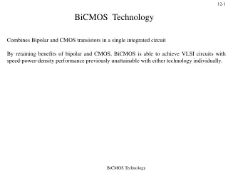
BiCMOS Technology
In this lecture, you will learn • advantages and disadvantages of bioplar and CMOS transistors • several schemes of integrating bipolar and CMOS devices on the same chip • Read : • 1. C.Y. Chang and S.M. Sze, “ULSI Technology”, McGraw-Hill, (1996), pp. 502-510. • 2. R.C. Jaeger, “Modular Series on Solid State Devices, Vol V : Introduction to Microelectronic Fabrication”, Prentice-Hall, (2002), pp. 262-263.
Advantages of Bipolar Transistors • High transconductance. • Very high speed, in the form of emitter-coupled logic (ECL) circuit. • High current driving capability – can charge large capacitative loads rapidly. • Disadvantages of Bipolar Transistors • High static power consumption. • Low packing density. • More complex fabrication process.
Advantages of CMOS Transistors • Very low static power dissipation. • Very high packing density. • Flexibility of circuit design. • Disadvantages of CMOS Transistors • Lower transconductance than bipolar transistors. • Small geometry MOS devices cannot provide sufficient currents to drive high capacitative loads, such as those associated with output pads and long interconnect lines.
BiCMOS Structures • The advantages of bipolar and CMOS transistors can be combined by fabricating both kinds of devices on the same IC Chip. • This is especially useful in mixed-signal ICs, where CMOS circuits are used for data storage and low power, high density logic circuits, while bipolar transistors are used for high current drivers. • BiCMOS circuits are found mostly in application specific ICs (ASICs) and very high speed static random access memories (SRAMs).
Triple Diffused BiCMOS structure Fig. 1 : BiCMOS structure formed by the addition of an npn bipolar transistor by the triple diffused process.
Based on a CMOS fabrication with the addition of one mask to form the base of the bipolar transistor. • The NMOS is built in a 10-15 m thick p-epitaxial layer on top of a p+ substrate. • The PMOS is built in an implanted n-well 4-5 m deep. • The n-well also serves as the collector of the BJT. • An additional p-type implantation is used to form the base of the BJT. • The n+ emitter, the n+ collector contact of the BJT are formed at the same time as the drain and source of the NMOS. • The p+ base contact is formed simultaneously with the drain and source of the pMOS.
Disadvantages • The n-well is used for both PMOS and bipolar transistor. Their doping requirements are different. • This leads to high collector resistance. • There is no buried layer to reduce collector resistance.
Standard Buried Collector BiCMOS Fig. 2 : BiCMOS structure showing the buried n+ buried layers.
Starting with a p- substrate, n+ buried layers are formed by antimony implantation. • The n+ buried layers not only reduce the collector resistance, but also reduce the susceptivity of the CMOS to latchup. • An n-type epitaxial layer is then grown to serve as the n-well of the PMOS as well as the collector of the BJT. • A p-type implantation / diffusion into the epitaxial layer is carried out to form the p-well and the p-isolation for the BJT. • A shallower p-implant is used to form the base of the BJT. • The rest of the structure are then formed as in the previous example.
Disadvantages • The p- substrate limits the packing density because of the allowance of space to prevent punch through between adjacent collectors. • The n-type epitaxial layer has to be counter-doped to form the p-well of the NMOS. Counter doping can reduce the performance of the NMOS by degrading the electron mobility.
Twin-well BiCMOS Fig. 3 : (a) buried n+ implant; (b) buried p-implant self-aligned to buried n+ layer.
Fig. 3 (contd.) : (c) growth of undoped epitaxial layer, followed by LOCOS process; (b) boron channel stop implant after etch of field isolation regions.
Fig. 3 (contd.) : (e) final cross –section of the twin-well BiCMOS structure.
A p- substrate is used as the starting wafer. A pad oxide is grown and a nitride layer is deposited and patterned. Antimony is implanted into the windows and annealed to form the n+ buried layer. Meanwhile, a thick oxide is grown by the LOCOS process over the n+ regions. • A boron implant is then carried out to form the buried p-layer. The thick oxide serves as a blocking mask, thus ensuring that the p-implants are self-aligned to the n+ buried layer. • All oxide are removed form the surface . A thin (1-1.5m) undoped epitaxial layer is then grown. • The LOCOS process is repeated to form the n-well, p-well and p-isolation regions, which are self-aligned.
A well drive-in process is performed with the oxide cap in place. All oxide are removed form the surface. A pad oxide and nitride layer are formed and patterned to delineate the active areas, where the devices will be formed. A boron channel stop implant is then carried out. • Thick field oxides are grown over the areas not covered by the nitride. After that, normal CMOS and BJT processing steps are carried out to form the NMOS, CMOS and bipolar transistors. • Note that in the process, there is no counter doping of the epitaxial layer. • The self-alignment of the n-well, p-well and isolation regions eliminates the additional space needed to allow for alignment tolerance in photolithography.
Question If the BICMOS IC has advantages over the CMOS IC, what are its disadvantages ?