Download
1 / 41
420 likes | 659 Vues
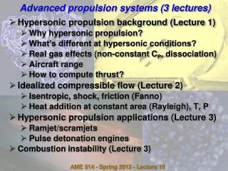
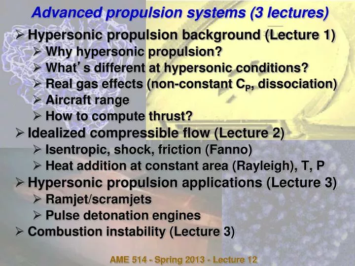
Advanced propulsion systems (3 lectures). Hypersonic propulsion background (Lecture 1) Why hypersonic propulsion? What ’ s different at hypersonic conditions? Real gas effects (non-constant C P , dissociation) Aircraft range How to compute thrust? Idealized compressible flow (Lecture 2)

E N D
Advanced propulsion systems (3 lectures) • Hypersonic propulsion background (Lecture 1) • Why hypersonic propulsion? • What’s different at hypersonic conditions? • Real gas effects (non-constant CP, dissociation) • Aircraft range • How to compute thrust? • Idealized compressible flow (Lecture 2) • Isentropic, shock, friction (Fanno) • Heat addition at constant area (Rayleigh), T, P • Hypersonic propulsion applications (Lecture 3) • Ramjet/scramjets • Pulse detonation engines • Combustion instability (Lecture 3) AME 514 - Spring 2013 - Lecture 12
Propulsion systems - performance parameters • Dimensionless figures of merit • Specific thrust = (Thrust)/(air mass flow)(c1) (c1: ambient sound speed) • Thrust specific fuel consumption (TSFC) = (Heat input)/(Thrust*c1) = (Fuel mass flow*QR)/(Thrust*c1) • Overall efficiency (o) = (Thrust power)/(Heat input) = (Thrust*u1)/(Heat input) = [(Thrust*c1)/(Heat input)][u1/c1] = M1/TSFC • Specific impulse = Thrust/(Fuel flow weight [on earth]) (units seconds) • Note TSFC = (1/ISP)(QR/c1gearth) not same as thermal efficiency • Thermal efficiency (th) = KE/(heat input) = [(u92 - u12)/2]/(fQR) • Propulsive efficiency (p) = (Thrust power)/KE = (Thrust*u1)/[(u92 - u12)/2] • Overall efficiency (o) = thp • TSFC = M1/o AME 514 - Spring 2013 - Lecture 12
“Conventional” ramjet • Incoming air decelerated isentropically to M = 0 - high T, P • No compressor needed • Heat addition at M = 0 - no loss of Pt - to max. allowable T (called T) • Expand to P9 = P1 • Doesn’t work well at low M - Pt/P1 & Tt/T1 low - Carnot efficiency low • As M increases, Pt/P1 and Tt/T1 increases, cycle efficiency increases, but if M too high, limited ability to add heat (Tt close to Tmax) - good efficiency but less thrust AME 514 - Spring 2013 - Lecture 12
“Conventional” ramjet example • Example: M1 = 5, T/T1 = 12, = 1.4 • Initial state (1): M1 = 5 • State 2: decelerate to M2 = 0 • State 4: add at heat const. P; M4 = 0, P4 = P3 = P2 = 529.1P1, T4 = T = 12T1 • State 9: expand to P1 AME 514 - Spring 2013 - Lecture 12
“Conventional” ramjet example • Specific thrust (ST) (assume FAR << 1) • TSFC and overall efficiency AME 514 - Spring 2013 - Lecture 12
“Conventional” ramjet - effect of M1 • “Banana” shaped cycles for low M1, tall skinny cycles for high M1, “fat” cycles for intermediate M1 Basic ramjet T/T1 = 7 AME 514 - Spring 2013 - Lecture 12
“Conventional” ramjet - effect of M1 • Low M1: low compression, low thermal efficiency, low thrust • High M1: high compression, high T after compression, can’t add much heat before reaching limit, low thrust but high o • Highest thrust for intermediate M1 Basic ramjet = 7 AME 514 - Spring 2013 - Lecture 12
Scramjet (Supersonic Combustion RAMjet) • What if Tt > Tmax allowed by materials? Can’t decelerate flow to M = 0 before adding heat • Need to mix fuel & burn supersonically, never allowing air to decelerate to M = 0 • Many laboratory studies, only three (apparently) successful test flight in last few seconds of sub-orbital rocket flight • Australian project: http://www.uq.edu.au/news/index.html?article=3414 • NASA X-43: http://www1.nasa.gov/missions/research/x43-main.html • Steady flight (thrust ≈ drag) achieved at M1 ≈ 9.65 at 110,000 ft altitude (u1 ≈ 2934 m/s = 6562 mi/hr) • 3.8 lbs. H2 burned during 10 - 12 second test • Rich H2-air mixtures ( ≈ 1.2 - 1.3), ignition with silane (SiH4, ignites spontaneously in air) • …but no information about the conditions at the combustor inlet, or the conditions during combustion (constant P, T, area, …?) • Real-gas stagnation temperatures 3300K (my model, lecture 10, slide 6: 3500K), surface temperatures up to 2250K (!) • USAF X-51: http://www.boeing.com/defense-space/military/waverider/index.html • Acceleration to steady flight achieved at M1 ≈ 5 at 70,000 ft for 140 seconds using hydrocarbon fuel AME 514 - Spring 2013 - Lecture 12
X43 AME 514 - Spring 2013 - Lecture 12
X43 AME 514 - Spring 2013 - Lecture 12
Component performance • Diffusers (1 2) & nozzles (7 9) subject to stagnation pressure losses due to friction, shocks, flow separation • More severe for diffusers since dP/dx > 0 - unfavorable pressure gradient, aggravates tendency for flow separation • If adiabatic, Tt = constant, thus d T2t/T1t = 1 and n T9t/T7t = 1 • If also reversible, d P2t/P1t = 1 and n P9t/P7t = 1, but d or n may may be < 1 due to losses • If reversible, d = d(-1)/ = 1, n = n(-1)/ = 1, but if irreversible d(-1)/ < 1 or n(-1)/ < 1 even though d = 1, n = 1 • Define diffuser efficiency d = d(-1)/ = 1 if ideal • Define nozzle efficiency n = n(-1)/ = 1 if ideal • For nozzle - also need to consider what happens if Pexit ≠ Pambient, i.e. P9 ≠ P1 AME 514 - Spring 2013 - Lecture 12
AirCycles4Hypersonics.xls • Thermodynamic model is exact, but heat loss, stagnation pressure losses etc. models are qualitative • Constant is not realistic (changes from about 1.4 to 1.25 during process) but only affects results quantitatively (not qualitatively) • Heat transfer model • T ~ h(Twall -Tgas,t), where heat transfer coefficient h and component temperature Twall are specified - physically reasonable • Wall temperature Tw is specified separately for each component (diffuser, compressor, combustor, etc.) since each component feels a constant T, not the T averaged over the cycle • Increments each cell not each time step • Doesn’t include effects of varying area, varying turbulence, varying time scale through Mach number, etc. on h • Work or heat in or out going from step i to step i+1 computed according to dQ = mdot*CP(Ti+1,t - Ti,t) or dW = -mdot*CP(Ti+1,t - Ti,t) (heat positive if into system, work positive if out of system) AME 514 - Spring 2013 - Lecture 12
AirCycles4Hypersonics.xls • Diffuser • Mach number decrements from flight Mach number (M1) to the specified value after the diffuser in 25 equal steps • Stagnation pressure decrements from its value at M1 (P1t) to dP1t = d/(-1)P1tin 25 equal steps • Static P and T are calculated from M and Pt, Tt • Sound speed c is calculated from T, then u is calculated from c and M • No heat input or work output in diffuser, but may have wall heat transfer • Shocks not implemented (usually one would have a series of oblique shocks in an inlet, not a single normal shock) AME 514 - Spring 2013 - Lecture 12
AirCycles4Hypersonics.xls • Combustor • Heat addition may be at constant area (Rayleigh flow), P or T • Mach number after diffuser is a specified quantity (not necessarily zero) - Mach number after diffuser sets compression ratio since there is no mechanical compressor • Rayleigh curves starting at states 1 and 2 included to show constant area / no friction on T-s AME 514 - Spring 2013 - Lecture 12
AirCycles4Hypersonics.xls • Nozzle • Static (not stagnation) pressure decrements from value after afterburner to specified exhaust pressure in 25 equal steps • Stagnation pressure decrements from its value after afterburner (P7t) to nP7t = n/(-1)P7tin 25 equal steps • Static P and T are calculated from M and Pt, Tt • Sound speed c is calculated from T, then u is calculated from c and M • No heat input or work output in diffuser, but may have wall heat transfer • Heat transfer occurs according to usual law AME 514 - Spring 2013 - Lecture 12
AirCycles4Hypersonics.xls • Combustion parameter = T4t/T1 (specifies stagnation temperature, not static temperature, after combustion) • Caution on choosing • If T1 < rT1 (r = 1 + (-1)/2 M12) (maximum allowable temperature after heat addition > temperature after deceleration) then no heat can be added (actually, spreadsheet will try to refrigerate the gas…) • For constant-area heat addition, if T1 is too large, you can’t add that much heat (beyond thermal choking point) & spreadsheet “chokes” • For constant-T heat addition, if T1 is too large, pressure after heat addition < ambient pressure - overexpanded jet - still works but performance suffers • For constant-P heat addition, no limits! But temperatures go sky-high • All cases: f (fuel mass fraction) needed to obtain specified is calculated - make sure this doesn’t exceed fstoichiometric! AME 514 - Spring 2013 - Lecture 12
Hypersonic propulsion (const. T) - T-s diagrams • With Const. T combustion, maximum temperature within sane limits, but as more heat is added, P decreases, eventually P4 < P9 • Also, latter part of cycle has low Carnot-strip efficiency since constant T and P lines will converge Const. T combustion, M1 = 10; M2 = 2.61 (T2 = 2000K) Stoich. H2-air (f = 0.0283, QR = 1.2 x 10⁸ J/kg = 35.6) AME 514 - Spring 2013 - Lecture 12
Hypersonic propulsion (const. T) - effect of M1 • Minimum M1 = 6.28 - below that T2 < 2000 even if M2 = 0 • No maximum M2 • overall improves slightly at high M1 due to higher thermal (lower T9) Const. T combustion, M1 = varies; M2 adjusted so that T2 = 2000K; H2-air (QR = 1.2 x 10⁸ J/kg), adjusted so that f = fstoichiometric AME 514 - Spring 2013 - Lecture 12
Hypersonic propulsion (const. T) - effect of • M1 = 10, T2 = 2000K specified M2 = 2.61 • At = 21.1 no heat can be added • At = 35.6, f = 0.0283 (stoichiometric H2-air) • At = 40.3 (assuming one had a fuel with higher heating value than H2), P4 = P9 • f & Specific Thrust increase as more fuel is added ( increasing), overall & ISP decrease due to low thermal at high heat addition (see T-s diagram) Const. T combustion, M1 = 10; M2 = 2.61 (T2 = 2000K) H2-air (QR = 1.2 x 10⁸ J/kg), (thus f) varies AME 514 - Spring 2013 - Lecture 12
Hypersonic propulsion (const. T) - effect of M2 • Maximum M2 = 3.01 - above that P4 < P9 after combustion (you could go have higher M2 but why would you want to - heat addition past P4 = P9 would reduce thrust!) • No minimum M2, but lower M2 means higher T2 - maybe beyond materials limits (after all, high T1t is the whole reason we’re looking at alternative ways to burn at hypersonic Mach numbers) • overall decreases at higher M2 due to lower thermal (lower T2) Const. T combustion, M1 = 10; M2 varies; H2-air (QR = 1.2 x 10⁸ J/kg), adjusted so that f = fstoichiometric AME 514 - Spring 2013 - Lecture 12
Hypersonic propulsion (const. T) - effect of d • Obviously as d decreases, all performance parameters decrease • If d too low, pressure after stoichiometric heat addition < P1, so need to decrease heat addition (thus ) • Diffuser can be pretty bad (d ≈ 0.25) before no thrust Const. T combustion, M1 = 10; M2 = 2.611; H2-air (QR = 1.2 x 10⁸ J/kg), adjusted so that f = fstoichiometric or P5 = P1, whichever is smaller AME 514 - Spring 2013 - Lecture 12
Hypersonic propulsion (const. T) - effect of n • Obviously as n decreases, all performance parameters decrease • Nozzle can be pretty bad (n ≈ 0.32) before no thrust, but not as bad as diffuser Const. T combustion, M1 = 10; M2 = 2.611; H2-air (QR = 1.2 x 10⁸ J/kg), adjusted so that f = fstoichiometric AME 514 - Spring 2013 - Lecture 12
Hypersonic propulsion (const. P) - T-s diagrams • With Const. P combustion, no limitations on heat input, but maximum temperature becomes insane (actually dissociation & heat losses would decrease this T substantially) • Carnot-strip (thermal) efficiency independent of heat input; same as conventional Brayton cycle (s-P-s-P cycle) Const. P combustion, M1 = 10; M2 = 2.61 (T2 = 2000K) Stoich. H2-air (f = 0.0283, QR = 1.2 x 10⁸ J/kg = 35.6) AME 514 - Spring 2013 - Lecture 12
Hypersonic propulsion (const. P) - performance • M1 = 10, T2 = 2000K specified M2 = 2.61 • Still, at = 21.1 no heat can be added • At = 35.6, f = 0.0283 (stoichiometric H2-air) • No upper limit on (assuming one has a fuel with high enough QR) • f & Specific Thrust increase as more fuel is added ( increasing), overall & ISP decrease only slightly at high heat addition due to lower propulsive Const. P combustion, M1 = 10; M2 = 2.61 (T2 = 2000K) H2-air (QR = 1.2 x 10⁸ J/kg), (thus f) varies AME 514 - Spring 2013 - Lecture 12
Hypersonic propulsion (const. A) - T-s diagrams • With Const. A combustion, heat input limited by thermal choking, maximum temperature becomes even more insane than constant P • … but Carnot-strip efficiency is awesome! Const. A combustion, M1 = 10; M2 = 2.61 (T2 = 2000K) H2-air (f = 0.0171, QR = 1.2 x 10⁸ J/kg = 30.1; (can’t add stoichiometric amount of fuel at constant area for this M1 and M2)) AME 514 - Spring 2013 - Lecture 12
Hypersonic propulsion (const. A) - performance • M1 = 10, T2 = 2000K specified M2 = 2.61 • Still, at = 21.1 no heat can be added • At = 30.5, thermal choking at f = 0.0193 < 0.0283 • f & Specific Thrust increase as more fuel is added ( increasing), overall & ISP decrease slightly at high heat addition due to lower propulsive Const. A combustion, M1 = 10; M2 = 2.61 (T2 = 2000K) H2-air (QR = 1.2 x 10⁸ J/kg), (thus f) varies AME 514 - Spring 2013 - Lecture 12
Pulse detonation engine concept • References: Kailasanath (2000), Roy et al. (2004) • Simple system - fill tube with detonable mixture, ignite, expand exhaust • Something like German WWII “buzz bombs” that were “Pulse Deflagration Engines” • Advantages over conventional propulsion systems • Nearly constant-volume cycle vs. constant pressure - higher ideal thermodynamic efficiency • No mechanical compressor needed • (In principle) can operate from zero to hypersonic Mach numbers Courtesy Fred Schauer AME 514 - Spring 2013 - Lecture 12
Pulse detonation engine concept Kailasanath (2000) • Challenges (i.e. problems…) • Detonation initiation in small tube lengths • Deceleration of gas to low M at high flight M • Fuel-air mixing • Noise AME 514 - Spring 2013 - Lecture 12
Steady Chapman-Jouget detonation engine • Recall (lecture 1) detonation is shock followed by heat release; whole spectrum of M3, but only stable case is M3 = 1 • Exploit pressure rise across shock to generate thrust after expansion • Can use usual compressible flow relations to expand post-detonation gas to Pe = Pa to evaluate performance • … but have to ignore low-H region - not realistic since temperature rise due to weak shock is insufficient to ignite mixture • Not practical since • Need to have exactly correct heat release (H), i.e. fuel-air ratio, to match inlet (flight) Mach number M1 • Not self-starting at M1 = 0 AME 514 - Spring 2013 - Lecture 12
Ideal DE (not P) performance AME 514 - Spring 2013 - Lecture 12
Tube length L “Uninformed” gas (u1 = 0) Reaction zone (2) Post - reaction zone (u3 = c1M1 - c3M3 = c1M1 - c3) “Stretched” or expanded gas (u4 = 0) ushock = c1M1,CJ Shock Thrust surface (Area A) Outside pressure = P1 PDE analysis • Assume gas in tube initially at rest • Propagate shock through gas (M = M1 CJ detn), compute T2, P2, M2 • Add heat to sonic condition (M3 = 1) for CJ detonation, compute T3, P3 • … (again) have to ignore low-H region - not realistic since temperature rise due to weak shock is insufficient to ignite mixture • Gas behind detonation is moving toward open end of tube, so “stretches” gas near thrust surface (closed end of tube),which must have u4 = 0 • Detonation structure is like piston with velocity u = c1M1 - c3, causes expansion wave: AME 514 - Spring 2013 - Lecture 12
PDE analysis Wintenberger et al., 2001 AME 514 - Spring 2013 - Lecture 12
Simplified PDE analysis • P4 acts on thrust surface for the time it takes the detonation front to reach the end of the tube and for the reflected wave to propagate back to the thrust surface ≈ L/(c1M1) + L/c4 • Not exactly correct because • Reflected wave speed > c4 (finite-amplitude, not sound wave) • Even after reflected wave hits thrust surface, still some additional expansion, but hard to compute because “non-simple region” (interacting waves) • More accurate analysis: Shepherd & collaborators (Wintenberger et al., 2001) • Impulse = Thrust x time = (P4 - P1)A[L/(c1M1) + L/c4] • Mass of fuel = mf = fuel mass fraction x density x volume = f1LV • Specific impulse = Impulse/(weight of fuel) = Impulse/mfgearth • Specific thrust & TSFC calculated as usual AME 514 - Spring 2013 - Lecture 12
PDE analysis CJ pressure = P3 Wintenberger et al., 2001 t1 = L/c1M1 t2 = L/c4 Pressure at thrust surface Post-expansion pressure = P4 Time AME 514 - Spring 2013 - Lecture 12
PDE analysis - hydrocarbon fuel • Performance unimpressive compared to turbofan engines (Isp > 10,000 sec) but simple, far fewer moving parts, can work at M = 0 up to hypersonic speeds AME 514 - Spring 2013 - Lecture 12
PDE analysis - hydrogen fuel AME 514 - Spring 2013 - Lecture 12
PDE Research Engine - Wright-Patterson Air Force Base • Pontiac Grand Am engine driven by electric motor used as air pump to supply PDE • Allows study of high frequency operation, multi-tube effects • Stock Intake Manifold with Ball Valve Selection of 1-4 Detonation Tubes Photos courtesy F. Schauer AME 514 - Spring 2013 - Lecture 12
Videos of H2-air PDE in operation Tube 1 @ 16Hz 4 Tubes @ 4Hz each 2 Tubes @ High Frequency Do PDE’s make thrust? Videos courtesy F. Schauer AME 514 - Spring 2013 - Lecture 12
Performance of “laboratory” PDE • Performance (Schauer et al., 2001) using H2-air similar to predictions unless too lean (finite-rate chemistry, not included in calculations) AME 514 - Spring 2013 - Lecture 12
Effect of tube fill fraction • Better performance with lower tube fill fraction - better propulsive efficiency (accelerate large mass by small u), but this is of little importance at high M1 where u << u1 AME 514 - Spring 2013 - Lecture 12
References • K. Kailasanath, “Review of Propulsion Applications of Detonation Waves,”AIAA J. 38, 1698-1708 (2000). • G. D. Roy, S. M. Frolov, A. A. Borisov, D. W. Netzer (2004). “Pulse Detonation Engines: challenges, current status, and future perspective,”Progress in Energy and Combustion Science 30, 545-672. • F. Schauer, J. Stutrud, R. Bradley (2001). “Detonation Initiation Studies and Performance Results for Pulsed Detonation Engine Applications,” AIAA paper No. 2001-1129 (2001). • E. Wintenberger, J. M. Austin, M. Cooper, S. Jackson, J. E. Shepherd, “An analytical model for the impulse of a single-cycle pulse detonation engine,” AIAA paper no. 2001-3811 (2001). AME 514 - Spring 2013 - Lecture 12