Download
1 / 20
220 likes | 382 Vues
Lithographic Aerial Image Simulation with FPGA based Hardware Acceleration. Jason Cong and Yi Zou UCLA Computer Science Department. Lithography Simulation (Application). Simulation of the optical imaging process Computational intensive and quite slow for full-chip simulation.

E N D
Lithographic Aerial Image Simulation with FPGA based Hardware Acceleration Jason Cong and Yi Zou UCLA Computer Science Department
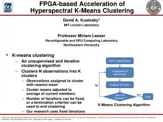
Lithography Simulation (Application) • Simulation of the optical imaging process • Computational intensive and quite slow for full-chip simulation
Socket-compatible : Replace one Opetron CPUwith the XD1000 coprocessor The module connects to the CPU's HyperTransport bus and motherboard DIMMs while utilizing the existing power supply and heat sink solution for the CPU. Dedicated DIMM for FPGA (not shared with CPU) Coprocessor communicates with CPU via hyper-transport link , has similar behavior as a PCI device Xtremedata Inc’s XD1000TM Coprocessor System (Platform)
Approach: Use of C to RTL Tools • Used two tools in our work • Codeveloper (Impulse C ) by Impulse Accelerated Technologies • AutoPilot by AutoESL Design Technologies • Advantages • Maintain the design at C level • Shorten the development cycle • Perform several tuning and refinement at C level • Loop interchange, loop unrolling and loop pipelining • Data distribution and memory partitioning • Data prefetching / overlapping computation and communication
Imaging Equations Loop over different rectangles Loop over pixels Loop over kernels I(x,y) image intensity at (x,y) yk(x,y) kth kernel fk(x,y) kth eigenvector (x1,y1)(x2, y2) (x1,y2) (x2,y1) layout corners t mask transmittance Pseudo code of the Imaging Equation
Loop Interchange Loop over pixels Loop over kernels Loop over layout corners Loop over kernels Loop over layout corners Loop over pixels Loop interchange • Different kernels do not have much correlation, thus put to the outer loop • Fix one specific layout corner, loop over pixels for more regular data access
Interpretation of Inner Loop after Loop Interchange • Imaging equation: • The loop over different layout corners and pixels: • The partial image computed by the inner sum is the weighted sum of shifted kernel, and how much is shifted is determined by layout corners Kernel Array - + Image (partial sum) - + Layout corners Object (one rectangle)
Loop Unrolling • Loop unrolling is one option to express parallelism in those tools • The improvementby loop unrolling is limited due to port conflicts • Data access of the same array cannot be scheduled to the same cycle due to port conflicts • May increase the initial interval when both loop pipelining and loop unrolling is used Loop unrolling
Further Parallelization needs Memory Partitioning • Unrolling did not solve the problem completely due to port conflictions • Need a multi-port (on-chip) mem with a large number of ports! • Implement the multi-port mem via memory partitioning • Computing tasks can be done in parallel once we get the multiple data in parallel • Each PE is responsible for computing one partition of image • Each PE composed of one partition of kernel and one partition of image partial sum • Multiplexing logic gets the data from different partitions of kernel and provides the data for each PE • To compute one partition of image, might also need the kernel data in other partitions Kernel partition 2 Kernel partition 1 Computing Element Computing Element Multi plexing Logic Image Partial Sum partition 2 Image Partial Sum partition 1 Kernel partition 4 One partition of Kernel Kernel partition 3 Computing Element Computing Element Image Partial Sum partition 4 One partition of Image Partial Sum Image Partial Sum partition 3 4-PE example
Choosing Partitioning Schemes • A less optimal partitioning design ( here is 2 x 2 example) • Block scheduling to avoid the data access contention ( at any time each PE accesses a different kernel partition) • Might face load balancing problem if required kernel data lie mostly in some partitions • Computing tasks is partitioned into blocks/stages PE 1 PE 2 PE 3 PE 4 Using Kernel Partition 1 Compute Image Partition 1 Using Kernel Partition 2 Compute Image Partition 2 Using Kernel Partition 3 Compute Image Partition 3 Using Kernel Partition 4 Compute Image Partition 4 Using Kernel Partition 2 Compute Image Partition 1 Using Kernel Partition 3 Compute Image Partition 2 Using Kernel Partition 4 Compute Image Partition 3 Using Kernel Partition 1 Compute Image Partition 4 Time Using Kernel Partition 3 Compute Image Partition 1 Using Kernel Partition 4 Compute Image Partition 2 Using Kernel Partition 1 Compute Image Partition 3 Using Kernel Partition 2 Compute Image Partition 4 Using Kernel Partition 4 Compute Image Partition 1 Using Kernel Partition 1 Compute Image Partition 2 Using Kernel Partition 2 Compute Image Partition 3 Using Kernel Partition 3 Compute Image Partition 4
partition 1 partition 2 partition 3 partition 4 Choosing Partitioning Schemes (Cont) • Data partitioning for load balancing • Here different colors different partitions • Memory banking using lower bits partition 1 partition 2 partition 3 partition 4 Image Partial Sum Array Kernel Array
Address Generation and Data Multiplexing • Need Address Generation Logic to provide the address for the kernel data and image partial sum as the memory is partitioned • Need data multiplexing logic to deliver the data from multiple memory blocks to the correct place • Implemented as 2D ring based shifting (better than naïve Mux on larger partitioning ) configuration 1 configuration 2 configuration 3 configuration 4 a 1 b 2 c 3 d 4 Start from: Reg_1=array_a[..] Reg_2=array_b[..] Reg_3=array_c[..] Reg_4=array_d[..] Wanted : Reg_1=array_c[..] Reg_2=array_d[..] Reg_3=array_a[..] Reg_4=array_b[..] Shift 1 step in Y direction Shift 0 step in X direction Reg_3 Reg_4 Reg_1 Reg_2
Loop Pipelining and Loop Unrolling • Loop pipelining can still be applied to the code after memory partitioning • Can speed up the code by a factor of 10X • Loop unrolling can be used to compact the code via multi-dimension array • One way to represent the memory partitioning kernel[size]; Loop body with unrolling pragma and pipelining pragma { …. +=kernel […]… //computation } kernel[4][4][size/16]; Loop body with unrolling pragma and pipelining pragma { …. +=kernel [i][j][…]… //if some index are constant }
Overlapping Computation and Communication • Use ping-pong buffers at Input and Output. • Two ways of implementation • Function / Block pipelining (AutoPilot) or Inter-Process Communication (Impulse C) SW HW HW DI1: Transferring Input From software to SRAM DI1 DI2 DI1 Comp Reading Input Data DI2: Transferring Input From SRAM to FPGA DI2 Reading Input Data Computation DO2 Comp Writing Output Data Computation Reading Input Data DO1 Writing Output Data DI1 DO2: Transferring Output From FPGA to SRAM Computation Reading Input Data Writing Output Data DI2 Computation DO2 Writing Output Data Comp DO1 DO1: Transferring Output From SRAM to Software DO2 DO1
Implementation Flow • Original code has nested loop • Loop interchange (manual code refinement) • Multi-PE implementation : add memory partitioning, address generation and data multiplexing logics (manual code refinement) • Enable loop pipelining for the refined code via specify pragmas • Use Impulse C and AutoPilot to compile the refined code • Use vendor tool to compile the RTL to bitstream • Run the program on the target system
Experiment Results • 15X speedup using a 5 by 5 partitioning over Opteron 2.2G 4G RAM • Logic utilization around 25K ALUT (and 8K is used in the interface framework rather than design) • Power utilization less than 15W in FPGA comparing with 86W in Opteron248 • Close to 100X (5.8 x 15) improvement on energy efficiency • Assuming similar performance
Experience on the Two Commercial Tools • Impulse C • Strong platform customization support • Hardware software co-design • Smaller subset of C • Autopilot • Support for both C/C++/System C • Larger synthesizable subset • Platform customization
Discussions • The performance without different optimizations • Roughly 2~3X worse if we do not do memory partitioning • Polygon based versus image based approach • Image based is 2D FFT • Which one is faster depends on actual layout • Implementation on GPU • The nested loop itself is already data parallel • G80 has very fast shared mem for thread blocks. But the size is only 16KB. • We had to put the kernel array in the texture memory with caching
Acknowledgments • Financial supports from • GRC • GSRC(FCRP) • NSF • Industrial support and collaboration from • Altera-AMD-SUN-XDI consortium • Altera, Magma, and Xilinx under the UC MICRO program • Valuable discussion and comments from • Alfred Wong (Magma) • Zhiru Zhang (AutoESL)