Download

1 / 63
630 likes | 665 Vues
Heat Pump Defrost Controls. Follows Pub No. 34-4101-07. Theory of Operation page 3. DFCs use a temperature sensing switch and a electronic timer circuits with on board relays to control the outdoor fan, switch over valve, heat strips and EDR

E N D
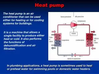
Heat Pump Defrost Controls Follows Pub No. 34-4101-07
Theory of Operationpage 3 • DFCs use a temperature sensing switch and a electronic timer circuits with on board relays to control the outdoor fan, switch over valve, heat strips and EDR • The DT is usually attached to the lowest circuits of the outdoor coil • The DT contact close at 40 degrees or below (Temp is not standard for all models check service facts)
Theory of Operationpage 3 • Compressor run time is accrued and memorized by DFC as long as “Y” call (24V AC applied between DFC Y & B Terminals) is made from indoor thermostat. When the DT switch contacts are open and the call for Y is removed the timers is reset to Zero and restarted on the next call on Y
Theory of Operationpage 3 • When the DT switch contacts are closed and the indoor thermostat terminate the call for Y. The timing is memorized and will resume on the next Y call. • The DFT Timer is activated when 24 VAC is applied to DFT R&B terminals. • The Test pins should not be jumped unless attempt is being made to speed up timer.
Theory of Operationpage 3 • A defrost cycle is initiated when the DT switch contacts close and the compressor run time has accrued the preset run time. • When Defrost is initiated, the DFC stops the out door fan, energizes the auxiliary heat and reverses the refrigerant cycle to the cooling mode by energizing the SOV.
Theory of Operationpage 3 • The Defrost cycle is terminated when the DT switch opens (50 to 70 degree outdoor coil temp.) or the 10 minute timer overrides has elapsed. • TST pins are shorted the timing is divided by 256 (90 minutes = 20 seconds)
Service Checkspage 4 • Short R to D • Momentary Short TST • Remove short when outdoor fan stops
24V Service Checks
24V Service Checks
24V Service Checks
Adaptability • The latest control models control models are applicable to many different heat pump products with up to 14 SEER ratings and minimize ID/OD mismatch and various electrical installation problems.
Logic Process • Microcomputer logic is used to monitor • Uses two remote sensors • Learning process
Defrost On Demand • Controls permit defrost only when coil icing conditions begin to cause serious heat pump capacity reductions.
Diagnostics • Detected faults displayed by flashing Light Emitting Diode (LED) on circuit board. • Board provides output signal that can flash emer. heat light on the indoor thermostat • Fault circuit not found on newest boards
Time Override • The Control prevents the system from being locked into the defrost cycle by automatic time termination.
Soft Switch-over • The outdoor fan comes back on 12 seconds before switch over valve coil is de-energized • This allows the Head pressure in system to be reduced • Lower Refrigerant Velocity • Prevents liquid hammer
Theory of OperationPage 10 • Uses Two Thermistor sensors
Theory of OperationPage 10 • ODS-B • Located just below the control box • with fan running senses ambient air temperature
Theory of OperationPage 10 • The DFC is power by the system 24V power • DFC is activated when 24V is applied between DFC R and B and the test lead is on the “NORM” pin • LED will flash once per second
Theory of OperationPage 10 • First power up with the outdoor temperature below 52 F and the coil sensor temperature is below 36 F and the control has counted 30 minutes of run time the DFC will initiate Defrost (2 min. run time) • DFC records clean coil Delta T • Next defrost will be on demand
Theory of OperationPage 10 • Defrost cycle is initiated when the current T exceeds the T initiate = current T X 2.0 + temperature bin correction factor • The initiate T is not a constant value, but is a value that the DFC calculated for a complete defrost cycle at that specified out door temperature.
Theory of OperationPage 10 • Ambient air sensor is turned off while DFC is in the defrost mode. • Defrost termination as soon as one minute • Memorized pre-defrost cycle ODT conditions are used to determine coil T terminate values.
Test ModesPage 11 • TEST MODE • To speed up defrost cycles times • Move Red jumper from NORM to TST • LED rapid flash
Test ModesPage 11 • FORCED DEFROST • Use instead of TST • Doesn’t Require sensors to enable
Test ModesPage 11 • FORCED FAULT • Not applicable to de-featured boards • move red jumper from normal to FRC FLT • reset by moving emer-switch on thermostat on and then off
Fault Detectionpage 13 • FAULT A • 2 quick Flashes per second • Low delta-T or low Heat Pump capacity • Inoperative compressor • Shorted coil sensor • Open ambient sensor • Flashes LED after three times Defrost terminates with Low delta T
Fault Detectionpage 13 • FAULT B • 3 quick flashes per second • Defrost terminates on maximum override time of 15 minutes instead of temperature • DFC will become timer defrost control after 10 consecutive terminations on maximum override • Every 30 minutes (not reported to thermostat)
Fault Detectionpage 13 • FAULT C • 3 quick flashes per second • Vary high delta-T • SOV stuck in heat mode • Inoperative solenoid • outdoor fan failure • open coil sensor • shorted ambient air sensor • Will reset if system returns to normal
Fault Detectionpage 13 • FAULT A and B or A and C • 4 quick flashes per second • 60 or more A faults and 1 or more B faults • 60 or more A faults and 1 or more C faults • Will flash fault light • Will reset if system returns to normal
Sensor CheckPage 16 • Measure the Temperature the sensor is exposed to. • When the coil sensor temp. is measured. You must measure tubing temperature that the sensor is measuring.
Sensor CheckPage 16 • Unplug the sensor from the DFC • Measure the resistance with a good quality Ohmmeter • Read the value as quickly as possible • This will prevent meter current from changing value K
Sensor CheckPage 16 Values Correct In Book • Using the chart on page 16 • Locate the closely as possible the actual sensor temperature • We measured a ohm value of 12.3K and a sensor temperature of 70 F 12.3K = 68.7
Service Checks • Must have 24V - 30V to R and B or control is brain dead
Service Checks • Must have 24V to 30V to Y and B also to initiate Defrost.
Service Checks • Insure that the sensor are OK • Measure Voltages at Y and B and R and B • Common and N.C on fan relay
ECM Control Fan Motor Page 19
New Generation De-featured ControlsPage 20 • Used with Reciprocating and Scroll Compressor Units • Last Quarter of 1998 eight New boards • Check Service Literature for suitable replacement • DFC for Scroll compressor time delay • MS control coil is powered by YO from DFT • Lite Port TM
“LITE PORT” • Emerging Technology • Will utilize Optical Coupler and Computer • Code from LED will be interpreted to gather more details of operation • You will see more on this in the future