Download

1 / 48
480 likes | 485 Vues
Explore the advancements in technology and instrumentation that have enabled high energy physics discoveries at the energy frontier, with a focus on designing a tracker for a collider detector. Learn about the challenges and solutions in achieving precise and fast silicon tracking, as well as the integration technologies and future developments in the field.

E N D
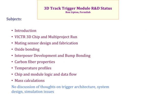
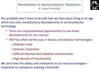
Instrumentation for the Energy FrontierRonald Lipton, Fermilab High Energy Physics has had remarkable success at the Frontier culminating with the discovery of the Higgs.This success was enabled by equally remarkable progress in technology and instrumentation. These lectures will look at past and current work and perhaps offer a glimpse of the future
Tracking Let’s think about designing a tracker for a collider detector • They all look pretty generic • The solenoidal field defines the overall geometry • Transitions from a barrel to disk geometry tend to be awkward • Disks provide lower mass at high eta, more normal incidence • The number of hits/area is maximized with disks combined with barrels D0
Designing a Tracker - 1 D0SMT • First let’s decide on the vertex detector • Scale set by HQ lifetimes • Minimize Rinner/Router • Rinner set by occupancy, beam pipe diameter • Router set by cost of pixelated detectors • smeas set by technology, mass of sensors • ILC ~ 5 microns at 1.5 cm (slow, rad soft, monolithic) • LHC ~ 20 microns at 5 cm (fast, rad hard, hybrid) • Length set by luminous region, angular coverage Tevatron luminous region ~25 cm long
Designing a Tracker - 2 • Momentum Resolution • Resolution proportional to s/BL2 • For a high momentum track f=f0+kr k=1/pt • We effectively want to measure Df (circumferential distance di) • Most important information is at the outer radius and near the origin • Intermediate layers primarily provide pattern recognition Alpha estimates the effectof the layer on momentum resolution
Designing a Tracker - 3 CMS FPIX Plaquette LHCB VELO R and F sensors • The Forward Direction • As we move forward the we begin to lose ∫Bdl and momentum resolution • Disks become more cost effective/hit than barrels • We can recover some momentum resolution with precision disks • We want to measure phi well, r not as well, but this is difficult in a disk geometry • Intermediate disks have little effect on resolution Tiled 3D pixel structure
Doublet strip modules For track trigger Doublet pixel/strip modules for track trigger Forward pixel diska For extended h coverage Possible design for CMS Phase 2 tracker with extension to improve acceptance for forward physics (H➛tt, Higgs self coupling, WW scattering)
Silicon Tracking This has become the “baseline” technology for the energy frontier. It is: • Precise ~ micron-level resolution • Moderate to low mass (depends on density, cooling, electronics) • Fast ~ can achieve sub-nanosecond resolution • Radiation hard – can be designed to operate to 1016/cm2fluence • Costly? $10/cm2 for CMS sensors $3/cm2 for CMOS electronics We can profit from the huge technical advances and infrastructure in the semiconductor industry
Signal and Noise • What is the thinnest “practical” silicon tracker? • Noise – Increasing gm costs power (gm~Id), minimize Cdet->pixels ~ 10 ff possibleminimal coupling to other electrodes • Power – assume id=500 na, pitch 25 microns • Signal – shoot for 25:1 s/n • 80 e/h pairs/micron • Speed – let’s say 5 ns • Mechanical – • Can thin to ~10 microns
Silicon Detector Analog cable SVX4 hybrid How we connect the detectors to the electronics, cool them, and mount them is the name of the game… Al SiO2 p+ n+ Hybrid Pixel Interconnect using bump bonds Analog cable SVX4 hybrid
Detector/Electronics Integration Technologies source top gate drain clear bulk ~1µm n+ p+ p+ n+ n+ + p s n i + x - - internal gate a - - - - - y 50 µm r t - e + m + m y s - - n p+ rear contact MAPS • Monolithic active pixels – collect charge in a few mm epitaxial layer (STAR, ALICE) • Charge coupled device (SLD) • DEPFET (Belle II) • Silicon on Insulator… • 3D Integration… CCD DEPFET 3D SOI
Solving Problems - MAPS MAPs – technology used in cameras using charge collection by diffusion in a thin(~5-15 mm) epitaxial layer Slow-charge collection by diffusion Low S/N Charge lost to parasitic PMOS Thick, high resistivity epitaxial layers 4 Well process 3D assemblies Fully depleted substrates (RAL) (IPHC-DRS) Thinning and backside processing (IPHC-DRS)
Technologies - Device-scaling Rapid initial decrease in cost • Slower leveling Voltage no longer scaling (P~CV2 f) Analog becomes harder at feature sizes below 65 nm Designs become very costly 8” 130 nm - $500k 12” 65 nm - $1.9M (Deptuch, IF ASIC meeting)
Technologies-Bonding Costs and Yields Current and projected costs and yields for sensor/readout integration technologies
Technologies-Three Dimensional Electronics Back-Face Face-Face A 3D-IC technology is composed of two or more layers of active electronics or sensors connected with through silicon vias • It enables intimate interconnection between sensors and readout circuits • It enables unique functionality • Digital/analog/ and data communication tiers • Micro/macro pixel designs • Correlate information • Wafer thinning enables low mass, high resolution sensors • Etching of vias (3D) through silicon bulk • Bonding technologies enable very fine pitch, high resolution pixelated devices • Commercialization of 3D wafer bonding can reduce costs for large areas • Unique circuit/sensor MIT-LL 3D-IC process FDSOI oxide-oxide bonding Ziptronix / licensed to Novati Xilinx 3D-based FPGA
Pixelization-3D Interconnect Copper bonded two-tier IC (Tezzaron) Technology based on: • Bonding between layers • Copper/copper • Oxide to oxide fusion • Copper/tin bonding • Polymer/adhesive bonding • Cu stud • Through wafer via formation and metalization 8 micron pitch, 50 micron thick oxide bonded imager (Lincoln Labs) 8 micron pitch DBI (oxide-metal) bonded PIN imager (Ziptronix) IBM 32 nm 3D technology PCB Interconnect
Opportunities in 3 Dimensions readout IC and pads 200 micron Buried oxide sensor trenches Handle wafer CMS Level 1 track trigger - Correlate hits in adjacent layers to filter out low momentum tracks Combine active edge and 3D electronics to produce tiled sensorscombined with ROICs for large area arrays CMS – Use stack of 3D tiers to emulatetracker layers for CAM –based trackrecognition Use TSVs to connect each SiPMsubpixel to quenching, timing, andcontrol electronics
Example - Track Trigger Via-Last Module (FNAL design) • 50 x 250 micron through silicon vias • Bump bonded short strip sensors • Analog signals through flex jumper • 2.5 cm long strips (set by chip size) In CMS the L1 trigger will be saturated with multiple interaction background • Use tracking information in the L1 trigger • Send hits from tracks with Pt>2 off detector for L1 • Correlate hits from sensors separated by ~ 1 mm • Correlation done on-module • To do this we need novel interconnect technology which allows the chip to “see” signals from top and bottom sensors • Through-silicon-vias allows single layer of electronics to see both TSVs 250m ROIC Analog signals Short (0.125 cm) strips Short (1.25 mm) strips Flex Jumper Carbon Foam Spacer Long (2.5 cm) strips
High Speed silicon Two techniques to attain ~10 ps resolution • Fast parallel plate structure using 3D detector technology • Use amplification to produce a large signal from initial electron arriving at gap structure Fast parallel plate structure (Da Via) Gain-based structure(Sadrozinski) Use two layers of 3D SiPMs to produce fast, low power, low noise trackers (Lipton)
Radiation Damage in Silicon • Radiation • Electromagnetic (g, b, x-ray). • Ionization, e-hole pair creation. • Hadronic (n, p, p). Damage to the bulk material caused by displacement of atoms from lattice sites in addition to ionization • Electronics are affected primarily by ionization • Charge buildup in insulating layers • Charge injection into sensitive nodes • Sensors are affected by bulk damage and ionization • Crystal structure damage • Introduction of traps • Introduction of mid-band states A. Vasilescu (INPE Bucharest) and G. Lindstroem (University of Hamburg),Displacement damage in silicon, on-line compilation
Radiation effects on Detectors extrapolated values electrons holes Ref 4. • HEP silicon detectors used at the Tevatron and LHC are primarily affected by bulk damage. Associated electronics are affected by primarily by ionization damage. • Detectors are unique • Lightly doped silicon • Thick structures • Regular array of electrodes • Several different bulk effects: • Increase in leakage current • Changes in doping concentration • Increased charge trapping • All of these depend on time and temperature, sometimes in complex ways Depends on temperature
Designing Radiation Hard Electronics • Radiation generates e-hole pairs in insulating oxides • Electrons are mobile and are removed by the gate-substrate field • Holes are trapped – either in the bulk or by deeper traps near the silicon-oxide junction • Holes can recombine with tunneling electrons from the silicon-> thin gate oxides in modern deep submicron electronics are intrinsically radiation hard Tranisistor DV/Rad Gate thickness (nm)
Designing Radiation Hard Detectors • Leakage current is universal • Generates shot noise, thermal effects • Reduce thickness • Run cold to reduce current, avoid thermal runaway • Trapping reduces signal mean free path • Thin detectors • Increase internal fields • Run Cold (~-20 deg C) • Freeze-in p-type impurities • Use 3D detectors • Etch electrodes deep into silicon • Full thickness for charge collection, short drift distance • Use Diamond sensors (Parker, Kenney)
Mechanics CMS These are complex engineered systems • Mechanics has central effects on physics performance • We sometimes focus too much on “physicsey” things like radiation damage and give short shrift to mechanics
Material • Controlling material is critical to physics performance. • That is apparent in vertex detectors and trackers, where multiple scattering limits spatial and momentum resolution. • The production of additional particles increases backgrounds and occupancies and complicates track finding, track tracing, and event reconstruction. • Stability, deflections, and distortions depend on the weight to be supported, the geometry of structures, environmental changes from fabrication to operation, and material properties.
New Materials • Carbon fiber composites • Carbon derivatives (C-C, Pyrolytic graphite, etc.) • Beryllium • Titanium alloys • Ceramics • Advanced compounds (SiC, BN, SiN, diamond, etc.) • Conducting polymers and carbon conductors • Foams • Adhesives • Electrical circuit components • Liquid / 2-phase cooling tubes
Power Current LHC detectors dissipate more than half their power in the cables. Future, more ambitious detectors will utilize even more power: • High speed front end electronics • GHz Waveform digitizers • Pixelated sensors • Higher readout bandwidth To address these problems all future experiments are examining power delivery options • Pulsed power (ILC, CLIC) • DC-DC conversion (CMS, ILC, CLIC) • High efficiency, rad hard high voltage ratio converters capable of operating in a magnetic field. • Serial powering (ATLAS, think Xmas tree lights)
Cooling An efficient, low mass cooling scheme should have: • Efficient heat transfer (2-phase) • CO2 systems • Low mass • Good thermal contact to electronics and sensor • Well engineered • Almost all hadron collider experiments (except D0) have had serious cooling issues Super B, LHCbmicromachinedchannels DEPFET air cooling thermal tests
Power and Cooling Readout Amplifier • Data transmission – 10-200 pj/bit ~ 5-10 Gbit/sec • Amplifier/readout ~100 mW/cm2 • Sensor IL ~ 1ma/100 cm2 x 500 V (high radiation) @ -25 deg C • DC-DC converter supplies power at 60-80% efficiency 5x10 cm module – 7.5 Watts If our tracker is 100 m2 -> 150 kW !!! Data Transmission Pixelated Sensor DC-DC conversion Support structure Cooling pipes
What do we do? • Data transmission • Low power (less rad had?) transmission (10pj/bit) • Lower bandwidth (process on detector) (2.5 Gb/sec) • Amplifier/readout • Low power design – limit functionality? • Smaller feature size no longer too helpful (Vdd~1V) • May be be able to achieve 75 mW/cm2 • Thin Sensor to 100 microns • Vd~T2, lower volume 0.3 ma @ 50V • High frequency DC-DC converter • 90% efficiency Can get to 85 kW – not so different than current CMS
Data Transmission Industry is driving low power, high bandwidth data transmission • Low power optical data transmission • Modulators rather than laser diodes • Mach-Zender – interferometer utilizing material with strong electro-optic effects • Radiation hard transceivers Current driver Laser (VCSEL) Optical Tx Elec. Tx Receiver PIN diodes Optical Rx Elec. Rx Laser (CW) Elec. Tx Modulator Voltage driver Optical Tx Elec. Rx PIN diodes Receiver Optical Rx Monolithically integrated Silicon photonic device
Muon Collider - Accelerator A muon collider would accelerate and cool a beam of muons and bring them into collision for ~1000 turns in a circular collider • It is the only lepton collider that can plausibly scale beyond 2-3 TeV with acceptable cost and power • Given the lack of new physics at 8 TeV LHC such a capability becomes increasingly interesting • Physics capabilities are similar to e+e- colliders, with additional ability to explore s-channel h and H/A, but worse beam background, lower polarization • It can provide a phased approach to implementation • Move gracefully from n factory to Higgs factory to high energy collider – complementing the rare decay and neutrino programs • The phasing and small footprint makes the program affordable • But the Muonbeam decays: • For 62.5-GeV muon beam of 2x10¹², 5x10⁶dec/m per bunch crossing • For 0.75-TeV muon beam of 2x10¹², 4.28x10⁵dec/m per bunch crossing, or 1.28x10¹⁰dec/m/s for 2 beams; 0.5 kW/m.
Ionization Cooling Muons produced by a high intensity target are collected and initially cooled by bunch rotation. • Ionization cooling is based on the idea that energy losss occurs in x,y,z but momentum is restored by RF in z only. • Cooling is limited by the heating effect of multiple scattering • Low Z absorber in RF cavity with solenoid field Emittance change Energy loss cooling term Multiple scattering Heating term
Accelerator Challenges • Ionization Cooling • Very high field (40T) high temp superconducting magnets • 6 dimensional cooling • RF breakdown in magnetic fields • Seems to be solved • Neutrino radiation ( < 10% x DOE limit at site boundary?) • Probably OK at 3 TeV, harder at 6 TeV • Must limit length of straight sections (~ meters) • Magnet shielding from beam decay heat loads Are any of these deadly to the Muon Collider concept? – subject of MAP
Figure of merit: Integrated Luminosity/Wall plug power 𝑭𝒐𝑴 ∝ 𝑳TOT / PWT luminosity X 1031 per MW Review of HIGGS Factory technology options
Evolution of Muon Facilities Accum Compr 0.8 – 2.8 GeV 0.2–0.8 GeV PX2 (3 GeV, 3 MW) 1-3 MW Neutrinofactory Acceleration m Storage Ring Front End Proton Driver 235m Linac + 2RLA Target 4 MW Higgs factory 3-10 TeVMuon Collider PX4 (8 GeV, 4 MW) MAP Collaboration workshop (June 19, 2013)
Muon Collider Background – 1.5 TeV Detectors must be rad hard Dominated by neutrons – smaller radial dependence Non-ionizing background ~ 0.1 x LHC But crossing interval 10ms/25 ns 400 x
Muon Collider Detector Neutrons/cm^2/bunch How do we design a detector for a muon collider? • Start with design for physics – ILC, CLIC detectors • SiD is the best match • Background rejection is clearly the dominant issue • Design the machine-detector interface and model bkd • Understand the compromises needed to reject background • Is it plausible, what are the physics impacts?
Much of the Background is Soft e+/- m+ g m- h0 h+- e+/- m+ g And Out of Time m- h0 h+- Timing is clearly crucial to reduce backgrounds (Striganov)
Background Inside a silicon detector: Detector thickness • Background Path length in silicon detector vs de/dx Angled tracks dE/dX MIP Path in detector
Time of energy deposit with respect to TOF from IP Neutrons positrons electrons Compton High energy conversions soft conversions
Tracker Implementation Simulation of 6 ns peak,100 ps jitter100 x 1 mm pixel 65 nm Front end (J. Kaplon, CERN) In time slow k or p • Tracker sufficiently pixelated so background occupancy is acceptable • 20 micron vertex • 100 micron x 1 mm tracker • Multi-hit/waveform digitize hits within ~20 ns window with ~0.5 ns resolution • Plausible given signal/noise, power requirements • Track fit now includes time of hit to accommodate slower particles from IP Problems are really power and interconnect Pixel waveforms Out of time n, g … In time pion Threshold Chan N Chan M
SiD(ILC)-Like Tracker SiD-like tracker with CMS-like 100m x 1 mm strips 20 micron pixel Vertex barrel 50 micron pixel Vertex disks Tungsten absorber cone
Calorimeter Implementation 20 GeVp- No DR correction Fast timing will lose some information from neutrons Backgrounds form a pedestal in each cell – fluctuations determine resolution • Segmented total absorbtion calorimeter • Merge PFA and Dual RO concepts • Design to control neutrons • Utilize prompt arrival and EM shower shape to identify photons andelectrons 20 GeV p- With DR correction No slow neutron signal: Before Dual Read out correction: Mean: 15.5 GeV(reduced by 13.6 %) s: 1.21+/-0.04 GeV After DR correction: Mean: 20.5 GeV s: 0.68+/-0.02 GeV (Wenzel)
Event Yields • Based on counting experiment stepping the beam across the Higgs resonance • I expect that detector efficiencies and analysis cuts will reduce yields by 10-20% • These results will have to be confirmed with full simulation including background
Summary and Conclusions This was a glimpse of instrumentation at the energy frontier I gave short shrift to or, neglected many things: • Diamond detectors • Triggering • Data processing Hopefully our Instrumentation Frontier report will provide a more balanced overview. There are many opportunities for young people to get involved • at Snowmass • On LHC upgrades • Generic detector R&Dprojects
references • Particle Data Group web site • V. Radeka, Ann. Rev. Nucl. ParticleSci. 38 (1988) 217. • F. Sauli (GEM)Nucl. Instr. and Meth. A, 386 (1997), p. 531 • Spieler- http://www-physics.lbl.gov/~spieler/USPAS-MSU_2012/index.html • JaakkoHärkönen, GSI/FAIR/NUSTAR/S-FRS seminar, Kumpula 6 October 2008 • Systematic Errors and Alignment for Barrel Detectors, A. Seiden. Mar 1991. 8 pp. SDC-91-021 • Velo–D.E. Hutchcroft, Initial results from the LHCb Vertex Locator, Nuclear Instruments and Methods in Physics Research Section A: Accelerators, Spectrometers, Detectors and Associated Equipment, Volume 648, Supplement 1, 21 August 2011, Pages S49-S50, ISSN 0168-9002, http://dx.doi.org/10.1016/j.nima.2010.12.216. • Ren-yuan Zhu (CalTech) - http://psec.uchicago.edu/workshops/fast_timing_conf_2011/ • J.B. Birks, The Theory and Practice of Scintillation Counting, New York, 1964 • G.F. Knoll, RadiationDetection and Measurement,NewYork, 1989 • http://www.kip.uni-heidelberg.de/~coulon/Lectures/Detectors/Free_PDFs/Lecture4.pdf • David Neuffer – Introduction to Muon Cooling
Effect of dual read out correction: g ‘s from neutron Capture discarded 20 GeV p- No DR correction 20 GeV p- With DR correction Before Dual Read out correction: Mean: 15.5 GeV (reduced by 13.6 %) s: 1.21+/-0.04 GeV After DR correction: Mean: 20.5 GeV s: 0.68+/-0.02 GeV Hans Wenzel