Download

1 / 91
910 likes | 919 Vues
The Level Measurement Market. Point Level Theory of Operation. What is Point Level?. Point level or On/Off measurement indicates the absence or presence of material at a certain point in the vessel, pit, pipe, etc… Point level measurements are used for High Level Spill Prevention

E N D
Point Level • Theory of Operation
What is Point Level? • Point level or On/Off measurement indicates the absence or presence of material at a certain point in the vessel, pit, pipe, etc… • Point level measurements are used for • High Level • Spill Prevention • Stop Fill • Low Level • Stop Empty • Refill Indication • Pump Protection
Properties of Material • A Material’s physical property does not affect RF Admittance measurements. • RF Admittance uses the product’s electrical properties to make the measurement.
Typical Values A=4.4 sq In 2.1” Capacitance in pF Material Between Plates 2.1” K D=1” Vacuum 1.0000 1.000 Air 1.0006 1.0006 Polyeth. Chips 1.3 1.3 Soap Powder 1.55 1.55 Kerosene 1.8 1.8 Sand 4.8 4.8 Alcohol 33 33 D.I. Water 78 78 pF Dielectric Constant (K)
uS Conductivity (g) Scale
It Starts With The Capacitor k A C = AC d Conductive Plate Conductive Plate Dielectric Insulating Material
AC Factors that Affect Capacitance Distance Between Plates Distance Capacitance Distance Capacitance AC AC k A C = d
AC Factors that Affect Capacitance Area of Plates Area Capacitance Area Capacitance k A AC AC C = d
Factors that Affect Capacitance Dielectric of the Insulator AC Dielectric Capacitance Dielectric Capacitance AC k A AC C = d
The Tank and Probe form a Capacitor k A C = d Where: C= Capacitance in pF k= Dielectric Constant of material A= Area of the plates d= Distance between plates d A k air = 1 C k oil = 2
The Tank and Probe form a Capacitor k A C = d k air = 1 Where: C= Capacitance in pF k= Dielectric Constant of material A= Area of the plates d= Distance between plates d A k oil = 2 C k
Affects of Dielectric and Conductivity • Vertical Bare Probes 30 Water 20 C p (pF) 10 0 Inches of Level Bare Probe
Affects of Dielectric and Conductivity • Vertical Bare Probes 30 20 C p (pF) 10 Oil 0 Inches of Level Bare Probe
What Happens Inside the Unit? • The Sensor in the vessel generates standing capacitance. • The unit is calibrated to balance the standing capacitance on the bridge circuit.
What Happens Inside the Unit? • An additional amount of capacitance called preload is added to make the unit stable • When the sensor is covered by material, the capacitance increases on the sensor side exceeding the preload, causing the unit to go into alarm.
What Happens Inside the Unit? • Note – For ThePoint and Intellipoint electronic units each turn of the potentiometer will ad: • 4 pF per turn for Standard Sensitivity electronics • 1 pF per turn for High Sensitivity electronics • Z-tron III is available in standard sensitivity only.
What does all this mean? Because an RF Point Level switch relies on the electrical properties of the material we must pay attention to active length of the sensing element. Conductive materials – no problem. Because conductive materials will cause a dramatic change in capacitance as soon as they touch the tip, active length need only be a stub (1/2 inch active is OK) Insulating material – because the change in capacitance in insulating materials is based on the dielectric, some amount of sensor will need to be covered in order to exceed the pre-load and cause the switch to change state. (8 inches of active is a good rule of thumb. If you must have less, discuss with the factory).
3-Terminal Cote-Shield™ Probe(Typical Construction) Insertion Length A C.S.L. Three main parts of a three terminal sensor are – Active, Cote-Shield, and Ground C
Increase Surface Area for Greater Sensitivity(Bare Sensing Elements Only) WELD WELD ADD A HORIZONTAL SECTION INCREASE PLATE SIZE WELD EXTEND THE LENGTH
What about measuring Solids? • One of the great things about RF switches is versatility! • One switch can measure: • Conductive or Insulating liquids • Slurries • Solids
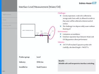
We can also measure Interface applications with RF point level. • Remember, we can set the switch to ignore the upper insulating phase and only respond to the conductive phase of the interface.
Properties of Material • A Material’s physical property does not affect RF Admittance measurements. • RF Admittance uses the product’s electrical properties to make the measurement.
False Alarm! False Alarm! Current flow No current flow Capacitance The Capacitance Disadvantage: • Affected by Conductive Coatings
False Alarm! False Alarm! Capacitance The Capacitance Disadvantage: • Affected by Capacitive shift due to temperature changes Capacitance of the mounting gland changes with temperature changes
The RF Advantage: • Not Affected by Conductive Coatings
Cote-Shield Mounting Consideration • Cote-shield must extend at least 50mm (2”) beyond the mounting and the typical expected wall build up.
Key Points • The basic formula for capacitance is C = K times A Divided by D. • We turn the customers vessel into a variable capacitor. • Calibration balances the bridge circuit for standing capacitance and adds a preload. • The switch will go from Normal to Alarm when the measured capacitance exceeds the preload.
Key Points • Conductive materials will cause a large (almost infinite) change on bare, un-insulated sensors. • Insulating materials will cause a smaller change in capacitance based on their dielectric. • RF Admittance uses electrical properties of materials to measure level. Physical properties such as viscosity and density have no affect.
RF Point Level Family Z-tron III™ General Purpose ThePoint™ Agency approvals Available with most sensing elements Intellipoint™ Agency Approvals Auto-Verify™, Dual Compartment Housing, SIL
IntelliPoint • The Intellipoint is our premium point level switch. • Dual compartment housing. • Integral or Remote mounting. • Auto Verify and Manual Certify standard • 0 to 60 second time delay (forward or reverse) • 100 amp spark protection built in • Auto ranging power supply (Relay Version)
IntelliPoint • Output • Relay (Line Power) • Two SPDT relays (One for alarm, one for fault) • Option for Gold Plated Relay contact • Current (two Wire) • 8mA Alarm/16mA Normal/22mA Fault Or • 8mA Normal/16mA Alarm/5mA Fault
IntelliPoint • Calibration • Auto calibration • Standard Sensitivity 2pF or 10pF preload • High Sensitivity 0.5pF or 2pF preload • Manual Calibration • Standard Sensitivity • High Sensitivity
IntelliPoint Products • Two Wire Intellipoint with SIL Rating • What is a Safety Instrumented System (SIS)? • A system designed to respond to hazardous or potentially hazardous plant conditions. The SIS is designed to take the process to a safe state when predetermined conditions are violated. • Also called Emergency Shut Down System (ESS or ESD) and Safety Shut Down (SSD) • A rigorous risk assessment is required to determine the appropriate Safety Integrity Level (SIL) for each process loop. Level range from SIL 1(lowest Risk) to SIL 4 (Highest Risk) • SIL Intellipoint conforms to SIL 2
Product FM Approved CSA Approved ATEX Approved Line Powered Intellipoint™, Integral Approved for use with FM approved Explosion Proof sensors only (See 420-0004-063 for list) Approved for use with 700-1202-021, 022, 024, and 028 Perm-A-Seal™ sensors only Approved for use with 700-1202-021, 022, 024, and 028 Perm-A-Seal™ sensors only Line Powered Intellipoint, Remote Approved for use with all sensors Approved for use with all sensors Approved for use with all sensors Two Wire Intellipoint, Integral Approved for use with FM approved Explosion Proof sensors only (See 420-0004-063 for list) Approved for use with 700-1202-021, 022, 024, and 028 Perm-A-Seal™ sensors only Approved for use with all sensors Two Wire Intellipoint, Remote Approved for use with all sensors Approved for use with all sensors Approved for use with all sensors IntelliPoint
ThePoint™ • Mid-Range RF point level switch • RF point level device is positioned in price between the Z-tron III and the Intellipoint • Single Compartment Housing • Integral or Remote mounting. • Available with all high use Sensing Elements • 0 to 60 second time delay (forward or reverse) • 100 amp spark protection built in
ThePoint™ • Output • Relay (Line Power) • DPDT relays • Option for Gold Plated Relay contact • Current (two Wire) • 8mA Alarm/16mA Normal Or • 8mA Normal/16mA Alarm
ThePoint™ • Calibration • Auto Calibration and Manual calibration are standard in ThePoint product. • Standard and High Sensitivity are also standard.
Product FM Approved CSA Approved ATEX Approved Line Powered ThePoint™, Integral Approved for use with FM approved Explosion Proof sensors only (See 420-0004-063 for list) Approved for use with 700-1202-021, 022, 024, and 028 Perm-A-Seal™ sensors only Approved for use with 700-1202-021, 022, 024, and 028 Perm-A-Seal™ sensors only Line Powered ThePoint, Remote Approved for use with all sensors Approved for use with all sensors Approval for use with all sensors Two Wire ThePoint™, Integral FM approved Explosion Proof sensors only (See 420-0004-063 for list) Approved for use with 700-1202-021, 022, 024, and 028 Perm-A-Seal™ sensors only Approval for use with all sensors Two Wire ThePoint, Remote Approved for use with all sensors Approved for use with all sensors Approval for use with all sensors ThePoint™
Z-tron III • Z-tron III™ is our economical general purpose point level switch • Integral Only • Available with general purpose PEEK Sensor 700-206- • 120VAC, 240VAC, or 24 VDC • Calibration through potentiometer
Z-tron III • 0 to 60 second time delay forward or reverse acting (Adjustable rotary switch) • 100 AMP Spark protection • The Z-tron III has General Purpose UL/CUL approval • CE Mark EEC Directive 89/336
Z-tron III • General Purpose Level Switch • OEM Accounts • Door Opener
Other RF Point Level Products • Multipoint – Line Powered point level offers 3 control points on one sensor • 506-3000 series • Three DPDT relays • 120 and 240 VAC • Multiple control points with one sensor (3 points) • One point can be set up as a differential for pump on/off control
Other RF Point Level Products • Clear Line – 506-7000 series • None intrusive sensor for absence or presence of material in a pipe • Pump Protection • Low level in lined vessels • Interface • DPDT Relay