Download
1 / 64
640 likes | 653 Vues
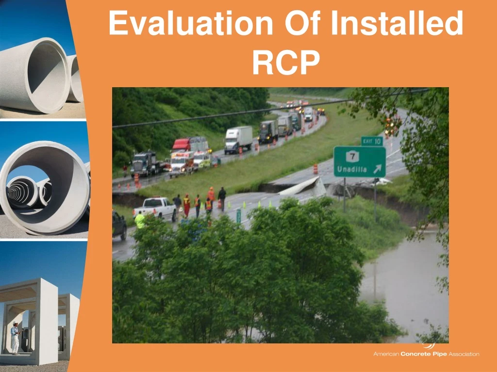
Evaluation Of Installed RCP. Goal. Give you information and tools to properly evaluate installed condition of RCP We want correct Evaluation of RCP PII & Asset Management = More Opportunities. Pipe Sweeping Across U.S.! New Install Acceptance & Asset Management. ME. VT. WA. MT.

E N D
Goal Give you information and tools to properly evaluate installed condition of RCP We want correct Evaluation of RCP PII & Asset Management = More Opportunities
Pipe Sweeping Across U.S.! New Install Acceptance & Asset Management ME VT WA MT ND MN NH NY OR WI MA ID MI RI SD WY CT PA IA OH NJ NE IN IL DE MD WV VA UT CO NV MO CA KS KY NC TN OK AR SC AZ NM MS GA AL AK LA TX FL Read More About it – ACPA ePipe – PII
Inspection - Tools and Techniques • Document Conditions • Inspection Methods • Advanced Tools
TOOLS – Remote Access AASHTO - SCOC
Evaluation Guidelines a MUST! • LESSON LEARNED!!!!!!
REVIEW OF BASICS What Zones would you anticipate a crack to form
Anatomy of a CrackRole of Reinforcement Role of Reinforcement? Where is crack the widest?
Key Components of Crack Evaluation Pattern/location + Size (width and length) = Severity
CRACKPATTERNS, • Longitudinal crack • Radial Tension Sheer • Circumferential crack Pattern + Size = Severity
Pattern – Longitudinal Crack Longitudinal Cracks: • result of load on pipe • Acceptable Location • 12 o-clock • 6 o-clock NOT Structural or durability Issue if only found at invert and obvert and < 0.05”
Pattern - Radial Tension Sheer Cracks • Cracks 30 deg off invert • Slabs of concrete can become dislodged • Slabbing is serious but can be repaired
Pattern - Circumferential Crack Not of Structural Concern, but may need remediation if backfill can move through crack.
Why are Circumferential/Transverse Cracks Not a Structural Issue?
CRACK PATTERNS –Review • Longitudinal crack • Load Induced • Not structural concern @ Invert & obvert • Watch for 5 & 7 O-clock and offsets across • Circumferential crack • Not structural concern or durability concern • Exception: width allows transport of backfill
AASHTO Const. Eval Guidelines Camera Only Remote Inspection Evaluation Criteria for Longitudinal Cracks: two longitudinal cracks the length of the pipe section is acceptable when the cracks are within 15 degrees of any quarter point of pipe, i.e 11 O-Clock to 1 O-clock, 2 – 4 O-Clock, 5 – 7 O-clock, and 8-10 O-Clock. Cracks at these points are signs of acceptable stress load cracks and are typically small cracks and do not allow soil infiltration and are not cause for concern unless the pipe is in an acidic condition (Ph of soil/runoff less than 5). Pipes with more than two longitudinal cracks the length of the pipe at the quarter points or pipe with cracks at 30 degrees +/- from invert i.e. 4-5 O-clock and or 7-8 O-Clock should be further evaluated by an Engineer with experience in RCP pipe design and evaluation. Any crack exhibiting significant vertical offset should be remediated www.concrete-pipe.org
Key Components of Crack Evaluation Pattern/location + Size (width and length) = Severity
AASHTO CRACK WIDTH CRITERIA • AASHTO section 27 • Cracks < 0.01 • Cracks > 0.01 evaluate to determine if detrimental • Cracks >0.10 In non-corrosive environments (ph>5.5) cracks up to 0.10” are considered acceptable
NCDOT - Cracks (Rigid Pipes): • Cracks > 0.01” and < 0.05” are acceptable. • Cracks > 0.05” but < 0.10” are acceptable unless the following additional conditions exist: • Minor repair is required if the pipe is located in an area of the state that exhibits corrosive soils.* • If vertical offset across a crack is exhibited, the following guidelines shall be followed: • When vertical offset is less than 0.10” provide minor repair. • For vertical offset greater than 0.10” a determination will be made by the Department on the repair method or acceptability of the pipe. • Cracks > 0.10” will be given consideration by the Department to replace the pipe or allow repair www.concrete-pipe.org
AASSHTO Sub Comm. Construction - PII/Eval. Guidelines Longitudinal cracks < 0.05" Evaluation Criteria: Pipe with cracks less than 0.05” shall be noted in the inspection report; however, no remedial action is required. Pipe with cracks greater than 0.05” and less than or equal to 0.1” and in areas where soil and or runoff Ph is 5.5 or greater shall not require remediation. Pipe with cracks greater than 0.05” and less than or equal to 0.1” and in areas where soil and or runoff Ph is less than 5.5 shall require remediation. Remediate or replace pipe having longitudinal crack widths larger than 0.10”. www.concrete-pipe.org
Crack Size – Summary Concrete pipe is designed to handle controlled size cracks. PASS THE DIME TEST!!! • Cracks < 0.05” No Concern • Cracks > 0.05 inch Consider Pattern & Ph
Joint Evaluation www.concrete-pipe.org
Evaluation Process for Joint Expectation • Required Performance • Compare Gap to Manufacturers allowable Gap • Evaluate Infiltration • Evaluate Structure Offset, Cracks, Chips, spalls
Rubber O-Ring Sealing Options = Performance Profile Rubber Gaskets www.concrete-pipe.org
Standard Practice for Pipe Joint Selection for Highway Culverts and Storm Drains – PP 63-09 Per AASHTO P 63-09, performance parameters can be divided into a hierarchy, with 4 main sub-groups: • Water Tight • Leak Resistant • Silt Tight • Soil Tight
Water-tight Joint: A joint that provides zero leakage of water infiltration and ex-filtration for a specified head or pressure application…. typically utilize a resilient rubber seal …..capable of passing a laboratory hydrostatic pressure and vacuum test of at least 10.8 psi without leakage. Pipe Joint Performance Parameters Leak Resistance: A joint which limits water leakage at a maximum rate of 200 gallons/inch-diameter/mile/day for the pipeline system for the project specified head or pressure.
Silt-tight: A joint that is resistant to infiltration of particles that are smaller than particles passing the No. 200 sieve. ….limit infiltration of the backfill material containing a high percentage of fines, …. utilize some type of filtering or sealing component, such as a elastomeric rubber seal or geotextile. Pipe Joint Performance Parameters Soil-tight : A joint that is resistant to infiltration of particles larger than those retained on the No. 200 sieve. Soil-tight joints provide protection against infiltration of backfill material containing high percentage of coarse grain soils,
Pipe Joint Performance Vs Joint Design Joint Performance Selection Considerations: **********AASHTO PP 63-09*********** Joint Material Specs: ASTM C 443 – Gravity Flow – Rubber Gaskets ASTM C 1628 – Gravity Flow - Rubber Gasket AASHTO M198.4 – Butyl Sealants ASTM C 877 – Exterior Wraps
Preformed Flexible Sealant Joints ASTM C 990 – Standard Specification for Joints for Concrete Pipe, Manholes and Precast Box Sections Using Preformed Flexible Joint Sealants. Intended to be soil and or silt tight.
ASTM 443 & ASTM C 1628 – Standard Specification for gravity Flow Rubber Gasket Joints Rubber Gasket Joints • Joint Design, Gasket • Hydrostatic head up to 30 feet • Leak Resistant • Laboratory tests: • a. 10 minutes, off centered at 13 psi • b. 10 minutes, deflected at 10 psi. Intended provide leak resistant joint.
Evaluation of Infiltration – Exfiltration www.concrete-pipe.org
Leak-Resistant Joint Evaluation • Requires Rubber Gasket • Minimal water flow through joint = OK • Gap less than Manufacturer = OK • Vertical offset less than 3/4” = OK • No crack larger than 0.05” in joint area = OK • No Chips or spalls that expose joint sealing material = OK
Silt-Tight Performance Evaluation • Joint Material = Rubber Gasket or Butyl + Wrap • Water infiltration allowed but must not transport fine material = OK • Gap less than Manufacturer = OK • Vertical offset less than 3/4” = OK • No crack larger than 0.10” in joint area = OK • No Chips or spalls that do not allow infiltration of backfill material = OK
Soil-Tight Joint Evaluation • Joint Material = Butyl Mastic • Water infiltration allowed and particles less than 200 sieve = OK • Gap less than Manufacturer = OK • Vertical offset less than 3/4” = OK • No crack larger than 0.10” in joint area = OK • No Chips or spalls that do not allow infiltration of backfill material = OK
NOTES TO INSTALLER & INSPECTOR Minimize ALL RCP Issues: • Handle with Reasonable Care • Provide Solid Foundation • Proper Bedding and Grade • Cannot Force on Grade • Proper Installation of Joint Materials • Cover Before LOAD – Careful with construction Loading
Evaluation Guidelines a MUST! NCDOT Guidelines for Post Installation Evaluation and Repair of Newly-Installed Drainage Pipe • Cracks/Slabbing/Spalling - RCP • Cracks Tears - Flexible Pipe • Deflection - Flexible Pipe • Joint Separations - All Pipe • Minor & Major Repairs – All Pipe
New National Evaluation Guidelines Available….AASHTO Const. Guideline Pipe Inspection and Evaluation Guidelines are available from AASHTO Subcommittee of Construction
“Sample Specifications for Evaluation of Newly Installed RCP
“Post Installation Evaluation and Repair Guidelines of Installed RCP” Background on : • RCP Loads • Design • Structural Confirmation • Joint Performance • Decision Matrix • Crack Evaluation & Repair • Joint Evaluation & Repair • Spalling & Slabbing Evaluation & Repair www.concrete-pipe.org
Contents • Background on RCP Loads, Design, Structural Confirmation, & Joint Performance • Decision Matrix • Crack Evaluation & Repair • Joint Evaluation & Repair • Spalling and Slabbing Evaluation & Repair
INTERACTIVE www.concrete-pipe.org
Examples and ApplicationStick our Head into some Pipe! Make Application of Crack and Joint Evaluation Discussion and Questions