Download
1 / 22
220 likes | 401 Vues
Introduction to Computer Systems (4). Hardware structures – system bus, internal (operational) memory. Piotr Mielecki Ph. D. http://www.wssk.wroc.pl/~mielecki. mielecki@wssk.wroc.pl. Piotr.Mielecki@pwr.wroc.pl. System Bus concept and example implementation. DEFINITION:.

E N D
Introduction to Computer Systems (4) Hardware structures –system bus,internal (operational) memory. PiotrMielecki Ph. D. http://www.wssk.wroc.pl/~mielecki mielecki@wssk.wroc.pl Piotr.Mielecki@pwr.wroc.pl
System Bus concept and example • implementation. DEFINITION: The bus in hardware structure of computer consists of a set of wires which connect the CPU with other parts of computer (memory and Input / Output devices in von Neumann’s architecture based computer). • The bus implemented in particular computer design for connecting its basic modules (not intended as widely used standard, like PCI, AGP etc.) is usually called a System Bus. • The basic problem rests on the fact that usually the same data and address lines (contacts) of the CPU microcircuit are used to make connection with different devices. So the System Bus has to separate form the CPU the devices which don’t take a part in particular connection (access cycle), enabling only those which are exchanging data right now.
Each implementation of the bus consists of 3 types of wires: • Address Bus – set of msignals (usually named A0 – Am-1) which pass the binary address to the device accessed for read (RD) or write (WR) operation (address in physical memory or in Input / Output space). If the CPU has address bus of 16 bit length (A0 – A15) it can address up to 216 = 65 536 different cells in memory, for example. The 32-bit address bus can address up to 4 GB (232 = 4 294 967 296) different bytes if the basic word in memory has 1-byte length. • Data Bus – set of n signals (D0 – Dn-1) which can pass the binary value to or from the device accessed for read or write operation (physical memory or I/O port). The length of the Data Bus is usually (but not always) equal to the basic machine word length of the particular CPU (8, 16, 32, 64 bit for example) and determines the class of CPU (“8-bit CPU”, “64-bit CPU” etc.). The data signals are bidirectional (inputs and outputs). • Control Bus – set of logical signals used to drive particular devices and access cycles like distinguishing between memory and I/O, reading and writing etc. The System Clock signal (CLK) which synchronizes all the devices is also a part of the Control Bus.
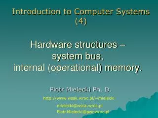
11 Vcc A0 30 A1 31 29 GND A2 32 A3 33 26 RESET A4 34 A5 35 6 CLK A6 36 A7 37 ADDRESS BUS 16 INT A8 38 CONTROL BUS 17 NMI A9 39 (INPUTS) A10 40 24 WAIT A11 1 Z-80 25 BUSRQ A12 2 CPU A13 3 A14 4 27 M1 A15 5 28 RFSH D0 14 18 HALT D1 15 23 BUSACK CONTROL BUS D2 12 (OUTPUTS) D3 8 19 MREQ DATA BUS D4 7 20 IOREQ D5 10 21 RD D6 9 22 WR D7 13 Zilog Z-80 CPU (modification of Intel 8080) – example of CPU’s System Bus.
To complete each data exchange cycle between the CPU and other device appropriate sequence of signals (“timing”) synchronized with CLK signal is needed. The control signals Read (RD), Write (WR) and Memory Request (MREQ) of the Z-80 CPU (for example) drive the attached memory circuits to enter read mode and complete the Memory Read access cycle or Operation Code Fetch (M1)cycle.
Most important and/or interesting things seen on the diagram are: • Control signals in most of circuits used to build microcomputers are active in “low” logical state (0 V). The signals MREQ and RD both have to be active to read from memory. • The rising edge of the CLK pulse causes the signals provided by the memory circuit and seen on Data Bus (D0 – D7 lines) to be copied (latched) to CPU’s internal data buffer register (see Lecture 3). • The lines D0 – D7 are the CPU’s inputs in reading cycle, the same lines are outputs in writing cycles. When the CPU or other device attached to the bus doesn’t have any data to write or read, it keeps its data lines in the logical “third state” (also called the high-resistance state), which is equivalent to electrically cut-off (R = ∞ Ω) from the external wires. • The processors like Intel 8080 and Zilog Z-80 were designed to co-operate with slow memory circuits, so they used to add entire CLK cycle (T2) between activation their MREQ and RD control signals and reading the data lines D0 – D7. It’s seen in both M1 and Memory Read cycles.
Memory hardware can force the CPU to add additional “empty” CLK cycles if memory circuits are not ready with data on Data Bus. It is possible with CPU’s WAIT input. • During the M1 cycle (T3 and T4 CLK pulses) Z-80 CPU supports the Refresh cycle for dynamic RAM (Random Access Memory) integrated circuits (today it’s not a common solution, the D-RAM modules have their own circuitry to do so). It is done by sending to 8 lower bytes of Address Bus (A0 – A7) the number of the entire raw in the RAM structure and activating the RFSH control output. The short pulse of MREQ signal causes the dynamic RAM circuitry (physically organized in a different mode this time) to rewrite it’s contents in one raw of cells. The CPU’s internal R register, which keeps the number of current raw in D-RAM structure, is then incremented by 1 for another Refresh cycle.
The Memory Write CPU cycle looks in a bit different way. This time the Write (WR) control signal together with MREQ causes the memory circuit (addressed by Address Bus lines A0 – A15) to read the data which CPU wants to write. The falling or rising edge of the WR signal should be used by the memory circuit to latch the data from Data Bus. Finally we can say, that System Bus (and any other bus) is defined by set of wires and sequences of control signals which drive different hardware devices during data-exchange cycles.
2. The operational memory – hardware implementation. • The internal memory (“operational memory” or “primary level storage”) should be implemented as a linear array of binary words (bytes, for example) addressed by a unique binary addresses. So it takes a part of “memory” in the von Neumann’s model of computer. • To be compatible with the System Bus the memory circuitry should have: • address inputs, • data inputs / outputs, • some control inputs (sometimes outputs like WAIT also). • In most of cases the set of control signals has to be passed trough additional logic circuits (decoders, logical gates etc.) to fit particular CPU circuit with memory chips used.
Simplified diagram of the Z-80 CPU attached to memory with System Bus.
From technological point of view we should distinguish between several types of memory circuits, for example: • RAM (Random Access Memory) – the circuits that can be written or read. Von Neumann assigned entire memory as RAM. Most of RAM implementations are the electronic integrated circuits which looses their contents after power-off. • SRAM (Static RAM) – the RAM circuits which don’t need refresh cycle. They are much faster than Dynamic RAMs, but have much less level of integration. Today used first of all as cache buffers between CPU and DRAM. • DRAM (Dynamic RAM) – RAM circuits of very high level of integration but with very short time of “remembering” the data. They have to be refreshed with special cycle provided by external generator (or CPU). The access time (speed) of standard DRAMs is much worse than in SRAM.
SDRAM (Synchronous Dynamic RAM) – DRAM which has a synchronous interface, meaning that it waits for a clock signal before responding to its control inputs (“normal” DRAMs have an asynchronous interface which means that they react as quickly as possible to changes in control inputs like RD or WR). The CLK signal is used to drive an internal sequential automat that pipelines incoming cycles. Pipelining means that the chip can accept a new access cycle before it has finished processing the previous one. In a pipelined write, the write cycle can be immediately followed by another cycle without waiting for the data to be written to the memory array. In a pipelined read, the requested data appears after a fixed number of clock pulses after the read instruction, at the same time additional access cycles can be sent to memory. • DDR RAM (Double Data Rate RAM) – SDRAM which reads or writes two words of data per clock cycle (one on rising edge, one on falling edge of the CLK pulse).
ROM (Read Only Memory) – the circuit which is written once (in the factory) and cannot be written with other data. • PROM (Programmable ROM) – the ROM chip which can be programmed by user (not inside the computer, with special device – programmer), but only once. • E-PROM (Erasable PROM) – the ROM which can be programmed and erased many times, but with external device (not inside the computer). Usually the ultra-violet (UV) lamp is the device which erases the contents of E-PROM. • EE-PROM (Electrically Erasable PROM) – ROM integrated circuit which can be erased and programmed electrically (without UV lamp), but still outside the computer. • NV-RAM (Non-volatile RAM) – RAM memory which can preserve its contents after switching-off the power. In older constructions the battery was mounted inside or outside the NV-RAM integrated circuit. Today the flash technology makes it possible without the battery, but we are distinguishing between NV-RAMs and flash memory making different use – flash technology is more suitable for large mass storage instead of magnetic disks (SSD – Solid State Disk).
3. The operational memory – more advanced organizations. • In most of today’s computers the operational memory is not organized exactly according to von Neumann’s concept. One of the first well-known modifications was the segmentation of the physical memory used by Intel in 16-bit processors 8086 and 8088 (introduced in first IBM-PC and XT in mid-1980-ties), now known as a “real mode” addressing in today’s Intel CPUs. The idea of segmentation came from the different roles that parts of memory can play: • The code of program is read-only in most of cases and the CPU processes it instruction after instruction (with branches sometimes). • The data processed (simple variables, arrays etc.) is read and written not sequentially rather (variables are located in different addresses).
The stack processed with CPU’s PUSH and POP operations is used in a different way than “normal” data area (we need to PUSH something to the stack before we can POP it back). But the stack plays very important part in the execution of the program, for example: • the return address is PUSHed on the stack before calling the subroutine and POPed from the stack on return from subroutine, • the parameters for the called subroutine are PUSHed to the stack by calling program and then POPed by subroutine, • local (“automatic”) variables declared inside the subroutine are usually allocated on the stack.
Intel’s designers assumed that up to 4 different segments of memory can be used by program at the same time: • Code Segment only for instructions (please notice that it corresponds with the Harvard Architecture concept), • Stack Segment only for (system or application) stack, • Data Segment for global variables and large blocks of memory (not “automatic”), • Extra Segment as the additional data segment. • According to this the processor has four 16-bit segment registers to support addressing in these independent segments: • CS pointing to the Code Segment, • SSpointing to the Stack Segment, • DSpointing to the Data Segment, • ESpointing to the Extra Segment.
The Address Bus in these processors was 20-bit length (could address up to 1 MB of memory). The address itself was not quite linear. It was calculated in each segment as the sum of two 16-bit values (segment + displacement) with 4-bit offset: To address the current instruction in the program CPU must have appropriate value in the CS register and in the dedicated index register, responsible for displacement in CS. This register is called Instruction Pointer (IP) and it’s value is added to value of CS in the way shown above. After each instruction cycle the value of IP is incremented by the length of instruction code. Stack segment is addressed by SS segment register and the displacement within this segment is pointed by index register Stack Pointer (SP) etc.
This implementation of segmented memory (only up to 16 fully separated, 64 kB segments was possible) was too poor to support multitasking operation system with several programs loaded into memory at the same time (although the CPM/86 or Concurrent DOS were designed, they were never widely used), so the MS-DOS was pure non-multitasking system. • First truly multitasking operating systems (OS/2, MS-Windows 3.0) were implemented on IBM-AT machines with Intel 80286 and newer processors, which could support memory in “virtual” (or “protected”) mode by more advanced hardware mechanisms.
4. Virtual memory – basic concepts. The concept of virtual memory assumes that the application can “see” the memory space much larger than physical memory installed in the computer. Using the technique called pagination the operating system, supported by some hardware solutions implemented in CPU, can map the desired, constant length (4096 bytes for example) block (called “page”) of this huge, virtual space into a block of physical memory (called “frame”). The idea of paginated virtual memory supported by Page Table.
Physical memory Logical (virtual) address Physical address P D F D CPU Page Table F Page No Frame No Calculating of the physical address in paginated virtual memory.
The CPU has the hardware mechanism which can detect, whether a desired page of virtual memory is present somewhere in the physical RAM (in any frame) or not (support for valid flag in the Page Table record, for example). • If not (valid flag set to 0), CPU rises an internal interrupt (exception) which starts system routine to find at last one free frame in RAM and reload the desired page from the swap area (usually in the mass storage). • If the free frame can’t be found,system must choose one of the used frames, write it’s contents (page) to the swap area (if the frame was modified since last loading from swap – the dirty flag is often applied in the Page Table record to mark this) and then replace it with the desired page. • In the operation systems which use the paginated virtual memory (practically all today’s multitasking systems) swap area is implemented as the special file (Windows) or the separated disk partition (Linux, UNIX etc.). The swap operation takes much time and makes the access to memory much slower than normal (“real-mode”) access cycle to physical memory. To avoid this problem (to minimize the number of swapping operations) advanced algorithms are implemented in operating systems for managing the pages.
Another problem is the length of the Page Table. Normally the page is a segment of memory 4 kB (4096 bytes) long. The 1 GB memory (1 073 741 824 bytes) should then be divided into 262 144 pages (or frames). Such a number of records in the Page Table would also take the space in memory, of course. To overcome this problem Page Tables are implemented not as single, constant-length arrays but as the lists or multilevel tables rather (Intel processors 80386 and newer, for example).