Download
1 / 67
770 likes | 1.07k Vues
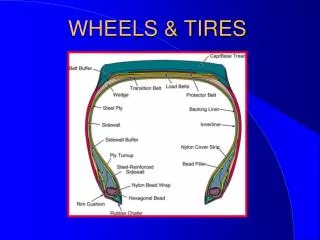
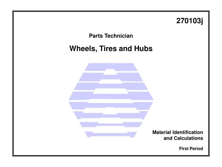
270103j. Parts Technician. Wheels, Tires and Hubs. Material Identification and Calculations. First Period. Figure 1 - Bias-ply construction. Figure 2 - Bias-belted construction. Figure 3 - Radial-belted construction. Figure 4 - Metric/imperial tire size format.

E N D
270103j Parts Technician Wheels, Tires and Hubs Material Identification and Calculations First Period
Figure 6 - Side wall markings including load and speed ratings.
Table 1 - Tire speed rating letters with corresponding speeds.
Table 2 - Tire load index rating numbers with corresponding weights.
Table 3 - Tire load range rating letters with corresponding plys.
Figure 8 - Tire manufacturers date code. (Photographed at Smart Automotive)
Figure 14 - Markings on a wheel indicating direction of rotation.
Figure 17 - Valve stem, Schrader valve and valve stem extensions.
Figure 19 - Wheel nuts. (Courtesy Toyota Canada Inc.)
Figure 20 - Tube type tire and multi-piece disc wheel.(Courtesy Freightliner of Canada Ltd.)
Figure 21 - Tubeless tire and disc wheel. (Courtesy Freightliner of Canada Ltd.)
Figure 22 - Tire tread designs. (Courtesy Freightliner of Canada Ltd.)
Figure 24 - Use care when off-loading inflated tires.(Courtesy Accuride Corporation)
Figure 25 - Cross-section of a five-piece rim assembly.(Courtesy Terex Americas - A Terex Company)
Figure 26 - Spoke wheel and hub assembly.(Reproduced with permission of Ford Motor Co.)
Figure 27 - Six-spoke wheel with a multi-piece rim assembly.(Courtesy Freightliner of Canada Ltd.)
Figure 30 - Hub designs with brake drums attached.(Courtesy General Motors of Canada Limited)
Figure 31 - Installed spacer and samples used in a dual tire application.(Courtesy Freightliner of Canada Ltd.)
Figure 33 - Tire cross-section with measurements defined.(Courtesy Freightliner of Canada Ltd.)
Figure 35 - Wheel stud and tapered nut. (Courtesy Freightliner of Canada Ltd.)
Figure 36 - Inner cap nut used to retain the inner wheel on a dual arrangement. (Courtesy Accuride Corporation)
Figure 37 - Flange-style wheel nut. (Courtesy Freightliner of Canada Ltd.)
Figure 38 - Hub-piloted dual wheel arrangement with flange nut installed.(Courtesy Accuride Corporation)
Figure 39 - Static imbalance. (Courtesy Toyota Canada Inc.)
Figure 40 - Dynamic imbalance. (Courtesy Toyota Canada Inc.)