Download
1 / 15
150 likes | 310 Vues
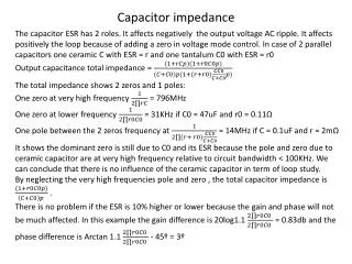
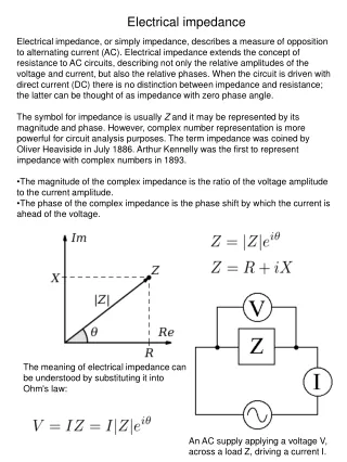
TCTP impedance. Benoit Salvant for the impedance team Many thanks to Elias, Hugo, Nicolas, Roderik and Stefano 22/04/2013. F oreword. Very preliminary…. New simulations with a cleaned model.

E N D
TCTP impedance Benoit Salvant for the impedance team Many thanks to Elias, Hugo, Nicolas, Roderik and Stefano 22/04/2013
Foreword • Very preliminary…
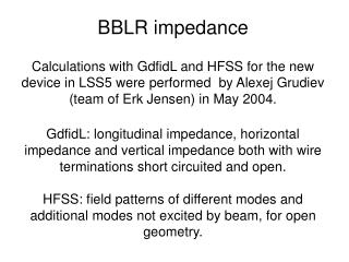
New simulations with a cleaned model • We redid some checks on the TCTP model and found that the low frequency mode at 100 MHz is quite large. Jaw half gap in mm Re(Z(f)) for a displacement of 0.3 mm Real Horizontal impedance for a displacement of 0.3 mm Frequency (GHz)
Impedance as a function of jaw half gap (not accounting for beta) 270 kOhm/m at 5 mm half gap and 80 kOhm/m at 10 mm half gap
What was the prediction in 2011 (impedance meeting Oct 17th 2011) I used 45 kOhm/m and beta function of 635 m. I am sorry I used an incorrect formula from frequency domain simulations to get Rsand it is on this value (45 kOhm/m) that we based our recommendation.
Conclusions of the impedance team at that time (Oct 17 2011) • New design already generates very large intensity effects below 3 mm half gap (due to new taper). • Open plate gap without ferrite seems unacceptable from power loss point of view. • Both other choices present risks from impedance point of view: • RF fingers: • Impedance of fingers seen by the beam? • no damping of longitudinal modes • Contact resistance not known • ferrite: • Decreasing the gap is not an option • Increase of low frequency transverse impedance (before 100 MHz) • Low frequency transverse modes are damped but present • Problem of knowing exactly the ferrite material and its specs It will be difficult to guarantee that the new design is at least as good as the old one…
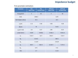
Parameters given by Nicolas and Roderik (B1H) Total horizontal real contribution at 100 MHz (B1H): 4.7 MOhm/m (about 20 % of the total real impedance at that frequency)
Parameters given by Nicolas and Roderik (B1V) Total vertical real contribution at 100 MHz (B1V): 5.5 MOhm/m (about 23 % of the total real impedance at that frequency)
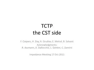
What was the prediction in 2011 (impedance meeting Oct 17th 2011) I used 45 kOhm/m (from the incorrect formula) and beta function of 635 m. Using the same scaling and with the corrected real impedance from time domain, we see that the first transverse mode would be damped by ~10 A in the octupoles. To be checked with the codes of Nicolas and Alexey and with Headtailmultibunch
Parameters given by Roderik for more pessimistic gaps With these more pesssimistic settings (8 sigma), the impedance at 100 MHz would be multiplied by ~2 to 3
What to do next? • Continue to validate the values obtained for the 100 MHz transverse mode • Check the impact of this transverse mode at 100 MHz on beam dynamics • Analytical codes of Alexey and Nicolas • Headtail simulations • Assess the impact of the other higher order modes • Understand why the frequency domain data are still off by a large factor (new release of CST enables computing the impedance with ferrite) • reassess heat load with the new models (original topic of this talk), but the error does not affect the computation of power loss.