Download
1 / 19
190 likes | 198 Vues
Understand the fundamentals of electricity and magnetism, including charge, current, circuits, and practical applications. Explore concepts such as conductors, insulators, static electricity, and lightning conductors.

E N D
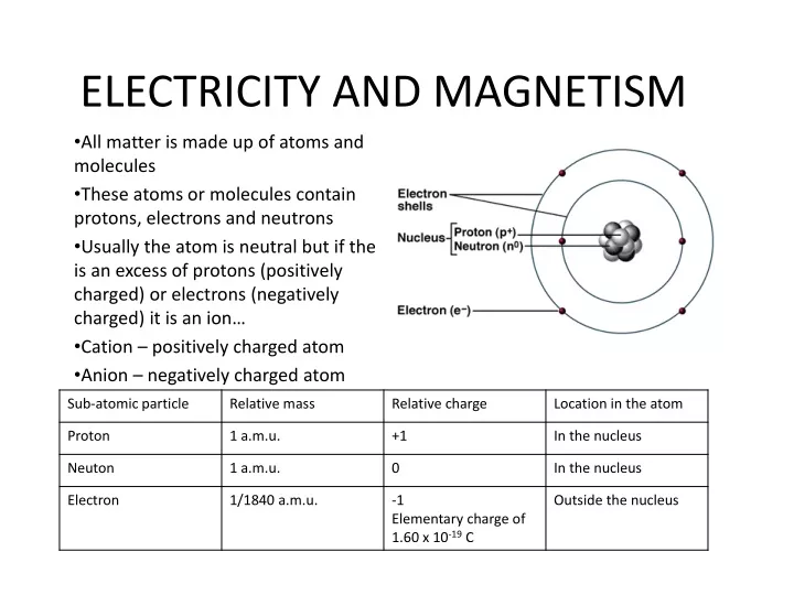
ELECTRICITY AND MAGNETISM All matter is made up of atoms and molecules These atoms or molecules contain protons, electrons and neutrons Usually the atom is neutral but if the is an excess of protons (positively charged) or electrons (negatively charged) it is an ion… Cation – positively charged atom Anion – negatively charged atom
Charge Carriers – is a particle or a group of particles which is associated with a certain quantity of excess positive or negative electric charge • Conductors are materials or devices which contain a significantly large number of mobile charge carriers which can move along a conductor in a specific direction when a voltage is applied across a conductor • Insulators are materials or devices that contain a small number of mobile charge carriers or immobile charge carriers (electrons bound firmly). Eg. Non-metals, plastics, glass, felt, rubber, paper, organic material, solid ionic compounds such as salts • Static electricity – the transfer of electrons to and from a material ( acquires deficient electron surfaces and deficient proton surfaces
Properties of charge: • Positive or negative • Like charges repel, opposite charges attract • Excess charge lies on the external surface of a charged conductor • Excess charge usually concentrate and accumulate where charged surface is sharply curved • Negative charges move from high region of concentration to low region of concentration however positive charge ‘move” from high electric potential to low electric potential • The Earth is at zero electric potential, is an infinite source for electrons and is a sink for electrons • Conventional flow of current in a circuit is in the direction of positive charge carriers • The principle of conservation of charge: whenever a quantity of charge of one sign is produced then an opposite sign is produced
Rate of directed flow of charge is called Current, I, it magnitude is I = Q/t where I – current, Q – given quantity of charge, t – time taken for movement past point Therefore Q = I x t and Q = n x q Where n – number of charge carriers passing a given point Q – charge on each one The unit of charge (Q and q) is called the Coulomb (C ) The unit of current is called the Ampere (A ) The unit of time is called the second (C ) One coulomb is 1 ampere per second
Lightning conductor • Clouds become negatively charged as air passes over it constantly (charging by friction) • A positive charge becomes induced on the roofs of buildings, lightning rods, etc. by the cloud • Ions flow to the rods and from rod to the cloud to neutralize some charges…reduction of chance of lightning striking • But if it does strike, charges flow to earth
Practical applications of charging • Spray painting – positively charged droplets of painting move towards earthed object following the lines of the electric field • Use of weedicides, pesticides, insecticides for crop sraying – charged droplets by use of sprayer so that they repel one another to create a wide spray, following electric field lines to move towards earthed plants • Dust extraction mechanisms – eg removal of dust in chimneys, etc. • Ink jet printers – control of ink droplets towards paper
Current electricity • The rate of flow of charge carriers essentially constitutes a current • In a circuit, the conventional flow of current is given by the direction of positive charge carriers (these don’t actually move)
Unit for electric current is the Ampere (A) defined as the force exerted between two straight, parallel, current-carrying conductors • Unit of electric charge is the coulomb defined as one ampere per second Q = I x t Q – charge, I – current, t –time Current may be d.c. or a.c. d.c. – direct current is the flow of current in one direction (variations on one side of the time axis) a.c. – flow of current in opposite directions over time…flow and reversed flow continuously (variations on both sides of the time axis)
CIRCUITS Fuse V Voltmeter Ammeter A /Rheostat Connecting wires Fuse used to prevent overflow of current Rheostat can be arranged to work as a Potentiometer (or potential divider… An arrangement for tapping off a variable fraction of an applied voltage.
Voltage or potential difference (or emf) across a circuit allows a current flow because the electrical energy is being converted to other forms of energy per unit charge flowing through it. • E. M.F. is the maximum voltage obtained between the terminals of an electrical power supply obtained such as from a cell. (chemical or kinetic energy converted to electrical energy
Resistance • In a circuit all components provide some resistance to flow of current dependent on the amount of load it is. • A resistance wire for example is dependent on the length of wire and is inversely proportional to its cross sectional area. It is also dependent on the nature of the material the wire is made from (silver, gold, copper and aluminum – low resistances)
Resistors in series • I = I1 +I2+I3…the same current flows through components in series • V = V1 +V2+V3…the total voltage across components in series is the sum of all the individual voltages • R = R1 +R2+R3…the total resistance of resistors in series is the sum of the individual resistances I1 I1 I2 V1 V2 V3 I2 I3 I3
Resistances in parallel • I = I1 +I2+I3…the same current flows through components in series • V = V1 +V2+V3…the total voltage across components in series is the sum of all the individual voltages • 1/R=1/R1 +1/R2+1/R3 …the total resistance of resistors in series is the sum of the individual resistances
Ammeters • Have a very low resistance compared with other devices in the circuit Voltmeters • Resistance of voltmeter is very large / infinite resistance to draw negligible current
OHM’s LAW • States that a voltage applied across a metallic conductor is directly proportional to the current through the conductor, provided that physical conditions remain constant. • V= I x R • For metallic conductors at constant temperature there is a linear relationship between V and I and a graph of V vs I is a straight line through the origin…Ohmic conductor. • Non Ohmic conductors do not have I-V graphs that go through the origin
House circuits • There are usually 3 wires used in household electrical wiring: • There are 3 wires from the pole to the house: 2 live 110V and 1 neutral • The Earth wire, a safety device provides an alternative route for current in case a live wire is touching the housing of an electrical device • A fuse or circuit breaker is also a safety device to minimize overload (eg a metal strip that breaks when too much heat is applied
Houses are usually wired with parallel wiring • So that each appliance can work independently • If any malfunction it does not affect the operation of other appliances • Each appliance can operate with the same voltages However, • Current surges can cause overload and lead to appliance damage and electrical fires • Current or voltage overload leading to a device operating below its rated power or not at all