Download

1 / 20
200 likes | 349 Vues
Background of Product. High Volume (1M-2M a year) Next Generation product in panel of 24Board level functional and ICT done at the same timeReduce time at product level functional test. What needed to be done. Switch in 3 resistors for each board positionnot enough GP relays to do this withEach

E N D
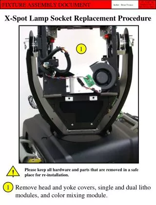
1. Automated Fixture Electronics Adding Fixture Electronic Boards into the board and board_xy
By
Thomas Garrison
2. Background of Product High Volume (1M-2M a year) Next Generation product in panel of 24
Board level functional and ICT done at the same time
Reduce time at product level functional test
3. What needed to be done Switch in 3 resistors for each board position
not enough GP relays to do this with
Each board to have one power supply muxed in
Also to have a series resistor
Keep test time, complexity, and maintenance low
Replacement easy and fast and done by anyone
4. Design Steps Decided to use analog switches as control element
Smaller footprint than relays, shorting blocks
Might be able to use a small kit
Number of devices needed reduced
18 Quad Switches vs 36 Dual relays
Decided to use analog switches and design board using ExpressPCB (http://www.expresspcb.com/)
Boards can be built be our internal house
5. What has to be part of the design 18 Quad analog switches (max365)
9 per module
96 Resistors
48 49 resistors
24 10k resistors
24 120 resistors for power supplies
~152 wires had to be connected
6. Internal vs. External External
Have to protect the circuitry
Probe points automatically generated for easier wiring
Good contact has to be maintained for each actuation
Internal
Everything away from prying eyes
Wiring more difficult with a ribbon cable
Have to remove interface plate to change or maintain
7. Design with ExpressPCB 35 mil square test pads on bottom of the board
spaced at least 100 mil apart
.125 diameter tooling holes
SOIC16 chips for the switches
1812 and 0603 chip resistors
Power supply resistors � watt through hole
Added extra breakaways for custom PCB for the 24 load resistors for the power supplies (boards placed internally)
Recorded X,Y locations of tooling locations and test pads in Excel file
8. Final Layout of PCB Board