Download
1 / 25
250 likes | 386 Vues
CFAC Review – Title II Design Status. Ove Dyling Assistant Director for Design Conventional Facilities NSLS-II Conventional Facilities Title II Design Status May 8, 2008. Agenda. Design Status Site & Utilities Ring Bldg Structural Ring Building Architectural Ring Building Mechanical

E N D
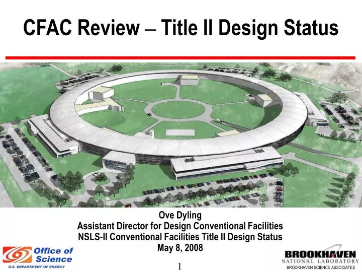
CFAC Review – Title II Design Status Ove Dyling Assistant Director for Design Conventional Facilities NSLS-II Conventional Facilities Title II Design Status May 8, 2008
Agenda • Design Status • Site & Utilities • Ring Bldg Structural • Ring Building Architectural • Ring Building Mechanical • Design Management Activities
Site & Utilities Design Revisions • Finished Floor Elevation • CD2 Finish Floor Elevation 70’-0” • Present Finish Floor Elevation 74’-0” • Process DI Water System • Relocated Cooling Tower to inside ring • CD2 design de-centralized distribution system • Present design centralized distribution system • Enlarged Cooling Tower Pump Building • Geotechnical • CD2 exploration program • Completed 16 borings • Present exploration program • Completed 75 additional borings
Ring Building Structural Design Revisions. • Expanded Steel width from 67’-0” to 77’-0” • Optimized concrete slab thickness • Experimental Hall from 18” to 15” • Storage Ring floor from 33” to 27” • Lowered finish floor elevation in storage ring • CD2 1’-4” above Experimental Hall • Presently 8” above Experimental Hall • Finalized top of building steel footing foundation below Storage Ring slab at 20”
RING SLAB Thickness Optimization ( to 27”)Service Building Slab Elevation Effect of slab thickness in 4-50 Hz range: 39” 2.62 nm 33” 2.85 nm 30” 2.97 nm 27” 3.00 nm
Assessment on Column/Footing Interaction Explored the following Options: Footing top @ 20” below mat bottom Footing top @ 36” Footing top @ 72” Footing bottom flush with mat bottom Recommendation: DESIGN with 20-inch separation between bottom of ring slab and top of footing
Detailed Models used in optimizing column footing depthOptimization was based on: Wind Loads and Vibration Transmission
Architectural Design Revisions. • LOB design program deferred to 2010 • Provide Toilet cores if LOB not constructed • Provide all future utility connections to LOB in Ring Building • Design for possible two stories • Design to accommodate future access corridor • Aligned Service Buildings with center of LOB’s • Rotated lattice 22.5 º clockwise • Long Beam lines • Added lowered exterior access corridor • Stairs, Mechanical and ADA lifts between long beam lines
Std Access Corridor By-pass Corridor Extended Experimental Floor Stair, ADA Lift and Material Lift Ramp
7’-1” 2’-6” Elevation Through Corridor At Beamline
Architectural Design Revisions Cont. • Service Building • Eliminated super doors • Reconfigured entrance labyrinth to Storage Ring • Provide removable shielding blocks to Storage Ring • Eliminated Elevator and provided crane access to second floor • Provided elevated slab on ground level to reduce vibration • Operation Center • Relocated control room to existing NSLS • Computer Room, telephone /data and UPS rooms remain • Future 3rd floor offices relocated to near front entrance as future alternate design
Architectural Design Revisions Cont. • Booster Building • Provided mezzanine to accommodate HVAC units and DI Water Systems • Revised labyrinth for tunnel entry • Revised injection transport region • RF Building • Expanded one bay to accommodate future RF cavities • Expanded mezzanine level to accommodate equipment/Control Room • Finalizing Compressor Building, Helium yard, and Liquid Nitrogen supplementary tank
RF Compressor Building Qualitative assessment completedQuantitative assessment under study Isolation joint
Mechanical Design Revisions Cont. • Fire Protection • Developed Fire Protection strategy for the Experimental Hall to receive waiver of $150,000,000 max loss potential limitation • Eliminated separation walls in Experimental Hall • Requested waiver for two hour separation between Experimental Hall and LOB’s and Service Bldgs in lieu of 3hr • Waiver approved but required additional redundancy for water supply, sprinklers and HSSD throughout • Process Utility Loads • Was a moving target however it is now finalized (final rev)
NSLS-II Process Utility Loads 425 598 2,596 CHW TWR * PCHW/PW split TBD 375* 518 613 157 1,640 50 80 182 300 1,240 970 30 1,160 35 580 300 2,275 1,740 Average AC Power Average Load kVA kW • Injector • Linac • Booster • BRF • xprt lines • SR Inst • Diag & Cntl • Vacuum • Interlocks • IDs • SR PS • Magnet PS • PS Cntls • SR • Magnets Cable Loss PCHW PW HVAC • SR RF • Cryo • SR RF • Controls • Klystrons • Loads • SR Vac • System • Absorbers • Chamber • Expt’l • Instr’t • Absorbers • Expt’l • Instr’t • Controls • Equipment • Acc. Loads Al ~ 1 MW transfers with electron beam Stays in SR RF in an upset condition
Mechanical Design Revisions Cont. • Storage Ring Tunnel • Added return air ductwork to assure temperature stability and meet smoke evacuation requirements • Temperature Stability modeling of the tunnel relative to earth berm and Experimental hall has been performed and determined to be within design parameters • Experimental Hall • Relaxed temperature stability to +/- 1 C - eliminated VAV boxes • Able to reduce beamline utility services by utilizing some services from storage ring tunnel (GN2, DI PCW) • Distributed return air to accommodate fire smoke exhaust
Mechanical Design Revisions Cont. • Process Water Systems • Revised from de-centralized system to centralized system • Centralized system located in Cooling Tower pump building • DI water system will be primary-secondary piping arrangement
Title II Design Management • Changes to design have used up available float for T-II • HDR agreed to maintain design delivery date of 8/25 • Required change to intermediate milestones • LOB design deferred to 2010 • Beamline support requirements will be better defined • A/E can focus on Ring Building design • Scope is frozen, only changes essential to Key Performance Parameters • A/E using added resources from other offices • Floor plans set, & all utility & process loads finalized (final rev)
Title II Design Management cont’d • Additional Design Scope • HDR is designing Central DI Process Cooling Water Plant • Scope transferred from ASD • Integrates tower water and DI PCW – long term operational savings • A/E Design to Cost Clause • Changes to scope/cost are being assessed and will be incorporated in revised Design to Cost Target for A/E • A/E still accountable for construction budget and to perform V/E • Issue is complicated by influence of volatile market and role of independent estimate provided by CM
Ring Building Package Scope • Ring Bldg Package Base Bid • Ring building w/ all site utilities but w/o LOBs • Beamline utilities to 60% of Ring • Exterior long beamline access corridor at LOB1-2 • Add Alternates • Extend Beamline Utilities remaining two pentants • Redundant Electrical Feed. • Shield Doors at all Ratchet Wall openings. • Clearstory windows at Ring Building. • Exterior wall panels at LOB (needed only if LOB not built) • Exterior access corridor LOB 2-3 • Exterior access corridor LOB 3-4 • LOB Package • 2 full LOBs, one shelled LOB • Lavatories and wall closure as needed for complete bldg
Title II Design Schedule • Original Title II Scheduled Milestones • Title II Design 30% Review Submittal Feb. 15 • Title II Design 60% Review Submittal May 15 • Title II Design 90% Review Submittal July 15 • Title II Design 100% Review and Bid Issue Submittal Aug. 25 • Revised Title II Schedule Milestones • Title II Design 30% Review Submittal Feb. 15 Completed • Title II Design 50% Review Submittal May 19 • Title II Design 80% Review Submittal June 23 • Title II Design 100% Review and Submittal Aug. 25 • Title II Design Bid Issue Submittal Sept 29th