Download
1 / 4
60 likes | 175 Vues
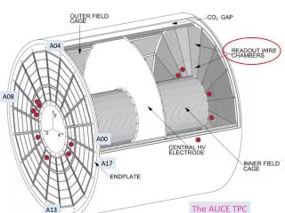
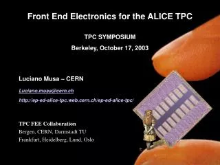
ALICE pictures. Definition of the front-end electronics and its cooling in the Alice TPC experiment. The Alice TPC is composed of the following elements which could be kept as principles for the LC TPC : The front-end electronic board (the size has to be redefined)

E N D
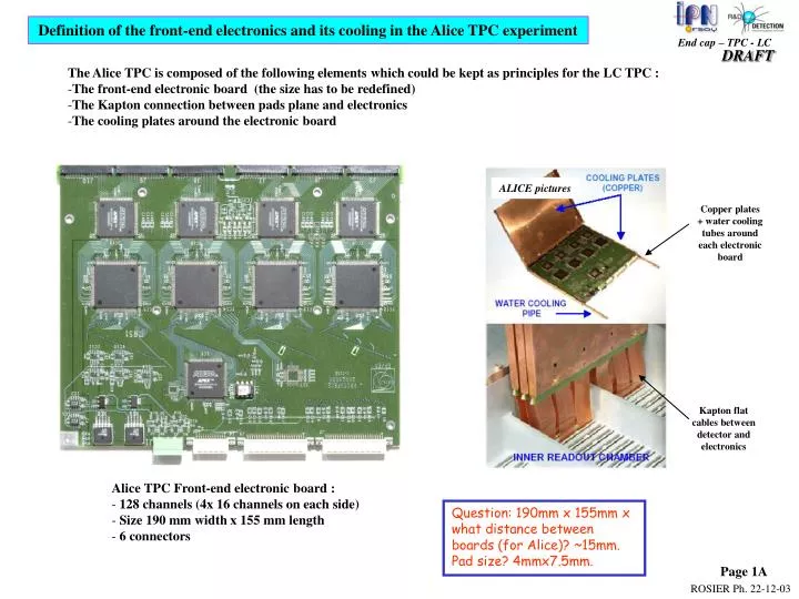
ALICE pictures Definition of the front-end electronics and its cooling in the Alice TPC experiment • The Alice TPC is composed of the following elements which could be kept as principles for the LC TPC : • The front-end electronic board (the size has to be redefined) • The Kapton connection between pads plane and electronics • The cooling plates around the electronic board Copper plates + water cooling tubes around each electronic board Kapton flat cables between detector and electronics • Alice TPC Front-end electronic board : • 128 channels (4x 16 channels on each side) • Size 190 mm width x 155 mm length • 6 connectors Question: 190mm x 155mm x what distance between boards (for Alice)? ~15mm. Pad size? 4mmx7.5mm. Page 1A
291.4 mm = 47 pads x 6.2 mm Pitch between boards = 16 mm 26 mm between connectors Connector 0.8 mm pitch (minimum standard) 80 channels Definition of a new electronic board and study of the implementation on the detector 1 The density of the Alice board is not enough (128 channels in 190 mm and 1.3 mm connector pitch). In the width to be considered (291.4 mm), we would get no space available around the connectors for the sandwich material (connectors everywhere). Assumptions: - Board with a density x 2 - Connectors 0.8 mm pitch. In the width of 291.4 mm, 2 boards of 140 mm width (length 130 mm) are placed. This board can have 160 channels and use 2 connectors of 80 channels each. That leaves 26 mm between connectors enough for the sandwich material. In the other direction, the distance between boards will be 16 mm (7 pads), which leaves 8 mm free for sandwich material. This assumption is illustrated below. We can adjust the pad size so that the electronics numbers come out ‘even’; e.g. 64pads x 4.55mm or 32pads x 9.11mm might be better. Also the 130mm length seems a bit much—maybe we have to demand a factor e.g. 4 more density… A pad width of 1.8mm and pad pitch of 2mm might be better, so that we get an ‘even’ number of 8 pads between boards might be better. Example of positioning the connectors on the detector 1: To read the 5500 channels, we need around 34 boards. Problem: Special boards are necessary in the non regular area. 2 boards by line Problem to solve: => Study of a high density electronic board Page 2
Kaptons Sandwich detector 1 Water tube WARNING ! The length of the boards is limited on the back by the TPC environment Some air can be pulsed between the sandwich detector and the cooling plate. Electronic board Inclined carbon plate for cooling and fixing the electronic boards Detector 1: Mounting and Cooling principles For the cooling, the electronics can be fixed and conductively linked on inclined carbon plates illustrated here below. The copper is replaced by carbon for low radiation length. The heat is evacuated on extremities by water tubes fixed on the horizontal carbon plate used also to hold the weight of the whole electronics. I like the water/air solution. Somehow we have to make sure that the kapton doesn’t block the air flow too much. Problem => The optimal inclination on the electronic boards needs studies to find the minimal radiation length Page 3
Information (available on WEB sites) on carbon material for the cooling Only the carbon fibers made from the “pitch” process have a good thermal conductivity coefficient. www.dau.mil/pubs/arq/99arq/traceski.pdf This behavior is unidirectional along the carbon fiber Page 16 on http://d0server1.fnal.gov/projects/run2b/Meetings/DOEReviews/Sep02/Parallel_Talks/Cooper_Sep02_silicon_mech.pdf => How is done exactly the connection between carbon plats and cooling tubes ? What is the whole efficiency ? (There is a ratio 1/100 between X-Y and Z directions) The manufacturer BP-Amoco is producing 3 types of fiber. The best is the K1100. http://www.electronics-cooling.com/html/2000_jan_techdata.html This fiber is commercialized in prepregs carbon/epoxy products by the society YLA (in USA) as an example => Is there any other distributor ? YLA society : http://www.ylainc.com/products/overview/overview.htm Carbon cooling devices have been studied in two experiments : - LHCb Inner tracker : Presentation by Frank Lehner of university of Zurich of carbon plates. An important R&D is on work on the improvement of the isotropic conductivity of the carbon material. => Is it possible to get a contact for further explanations ? lhcb-doc.web.cern.ch/lhcb-doc/progress/ Source/LHCC/Nov_2002/frank.pdf - D0 Run IIb : Presentation by Cooper from Fermi Lab about special development. Carbon tube and carbon plate assembled together. http://hepwww.rl.ac.uk/Vertex03/Talks/BillCooper.pdf Deep studies are necessary to evaluate the feasibility about technical and price point of view of such carbon elements. The matts of CF would be made of several layers. The directionnality can be used to direct the heat to the water cooling. Page 4