Download
1 / 14
140 likes | 339 Vues
CVD Diamond Dielectric Accelerating Structures *. P. Schoessow, A. Kanareykin (Euclid Techlabs), R. Gat (CTS Inc.), J. Butler (NRL). *Work supported by US DOE. Dielectric Structures at High Frequencies.

E N D
CVD Diamond Dielectric Accelerating Structures * P. Schoessow, A. Kanareykin (Euclid Techlabs), R. Gat (CTS Inc.), J. Butler (NRL) *Work supported by US DOE
Dielectric Structures at High Frequencies • Simplicity of fabrication: The device is simply a tube of dielectric surrounded by a conducting cylinder. This is a great advantage for high frequency (~30 GHz) structures compared to conventional structures where extremely tight fabrication tolerances are required. The relatively small diameter of these devices also facilitates placement of quadrupole lenses around the structures. • Dielectrics can potentially exhibit high breakdown thresholds relative to copper, and high shunt impedance. • Reduced sensitivity to the single bunch beam break-up (BBU) instability: The frequency of the lowest lying HEM11 deflecting mode is almost always lower than that of the TM01 accelerating mode. • Easy parasitic mode damping. Potential challenges of using dielectric materials in a high power RF environment are breakdown and thermal heating, although problems with dielectric charging are easily mitigated by using a dielectric with a small dc conductivity.
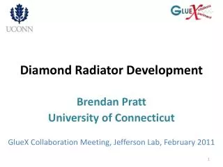
Overview • Development of a cylindrical diamond-based dielectric loaded accelerator (DLA) structure. • The electrical and mechanical properties of diamond make it an ideal candidate material for use in dielectric accelerating structures: • permittivity=5.7 • high RF breakdown level (GV/m), • extremely low dielectric losses (tan δ<10-4) • highest thermoconductive coefficient available (2×10³ Wm−1 K−1) . • The method we plan to use for fabrication of the diamond tubes is based on CVD (Chemical Vapor Deposition). • A sustained accelerating gradient larger than 600 MV/m, in excess of the limits experimentally observed for conventional copper cavities should be attainable.
CVD Diamond Manufacture • CVD diamond is made when a dilute mixture of methane (CH4) in hydrogen is chemically excited to produce atomic hydrogen and hydrocarbon radicals. • Diamond bond (sp3) slightly more stable under hydrogen bombardment than the graphitic (sp2). • In most commercial systems excitation is performed using microwave radiation; hot filaments also used • Microwaves partly ionize and cause intense heating of the gas mixture up to 4000°C. The diamond film forms on a surface held at about 900°C in proximity to the excited gas. Typical pressures are sub-atmospheric (100 Torr), film growth rates ~15 pm/hr depending on reactor design and power. • Turnkey microwave reactors capable of unattended diamond deposition over areas of up to 12” in diameter are commercially available • The present cost for relatively low quality CVD diamond is ~few hundred $/carat. (A carat of diamond is 200 mg or approximately a piece of size 10×10×0.6 mm3.)
Segmented Structures Highest diamond quality achieved with this process
CVD Diamond Surface and Multipacting Performance • Negative electron affinity (NEA) results in extremely high SEE (secondary electron emission) coefficients. Hydrogenated CVD diamond films possess a strong NEA with a high coefficient of secondary electron emission (up to ~60). • Dehydrogenated or oxidized diamond surfaces show a positive electron affinity and demonstrate SEE coefficients ~1 and consequently can be used as a dielectric loading material for the high gradient DLA structures with reduced or suppressed multipacting performance. • Diamond surfaces may be oxidized in a number of ways (e.g. oxidizing acid or oxygen plasma treatments), resulting in PEA. • CVD diamond bulk and films can be fabricated with a secondary electron emission yield ~1. • Requires that desorption of hydrogen from the diamond surface or oxidation of the surface. • Use of nitrogen or other CVD diamond dopants are being considered. • Study secondary electron emission surface properties by SEE spectroscopy methods planned at NRL.
CVD Diamond Surface and Multipacting Performance: Effects of Annealing • Secondary electron yields for hydrogenated single-crystal diamond surface before and after annealing at 950 °C. • Sharp decrease of the SEE yields (~1) after the annealing resulting in dehydrogenation of the diamond surface. Changes in the secondary-electron yield of CVD diamond after sample heating. 5 min at 500 °C 5 min at 500 °C Before heating 15 min at 1000 °C
34 GHz Structure Prototypes: Effect of Radial Vacuum Gap Diamond-based cylindrical DLA structure parameters in case of: (a) no vacuum gap, (b) 2 mm vacuum gap between the outer diamond surface and the copper wall. Note the high shunt impedance of 262 M/m for the vacuum gap case, and 152 M/m for the “no-gap” design. Surface field ratio Emetal/Eaccelerating > 0.17 for a 1.5 mm beam channel aperture.
34 GHz Structure Prototypes: Effect of Vacuum Gap A B Axial (red) and transverse (blue) electric field profiles along the structure radius, normalized to the acceleration gradient Eaccel. Diamond tube inner diameter 2a = 1.5 mm, outer diameter 2b = 3.79 mm, wall thickness is 1.15 mm; (A) No gap; (B) 2mm vacuum gap width.
Summary • We plan to develop and demonstrate a cylindrical Dielectric Loaded Accelerating (DLA) structure based on a diamond waveguide. • Use of CVD (Chemical Vapor Deposition) diamond as a loading material will allow high accelerating gradients up to 0.5-1.0 GV/m provided that the diamond surface can sustain a 1-2GV/m breakdown rf field as expected. • CVD process technology is rapidly developing; the CVD diamond fabrication process is becoming fast and inexpensive. • Multipacting performance of the CVD diamond can be dramatically suppressed by diamond surface dehydrogenation through annealing or chemical treatment.