Download
1 / 18
180 likes | 278 Vues
Michael I. Andersen Astrophysikalisches Institut Potsdam. Aligning robotic telescopes within the inversion layer (the life of the robotic optician). The challenge I. The seeing is fantastic! 0.27” median above the inversion layer (Lawrence et al. 2004) Is the telescope fantastic?

E N D
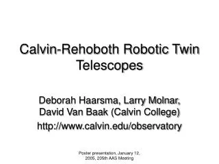
Michael I. Andersen Astrophysikalisches Institut Potsdam Aligning robotic telescopes within the inversion layer(the life of the robotic optician)
The challenge I The seeing is fantastic! 0.27” median above the inversion layer (Lawrence et al. 2004) Is the telescope fantastic? (to utilize the best seeing, the telescope essentially must be diffraction limited)
Challenge III The optician goes home with the last flight. There is no dark time to test and align. The temperature is completely wrong. There are 50 working days per season.
The challenge IV • As part of commisioning, to establish the initial alignment during summer, i.e. in daylight! • To maintain and optimize this alignment at temperatures 40 degrees below ‘commisioning temperature’, without much need for human intervention.
Two case studies • Small telescope, ‘ICE-T’, 60/80cm Schmidt (talk by Strassmeier) • Large telescope, ‘PILOT’, 2.4m ‘classical’ Alt-Az Richey-Cretien telescope (talk by Storey)
ICE-T • 2 x F/1.17 60cm Schmidt • 7.7deg square FOV. • Fixed passband. • 10k x 10k monolitic CCD
The ICE-T challenge • Keep the PSF stable, with a uniform defocus → passive design with self compensation Good optical quality mirror and good passive mirror support (corrector less important). Passive focus compensation (Aluminum + Aluminum) (Carbon fibre + CeSic (ΔCTE <2 x 10^-7) ) (Carbon fibre + Zerodur (ΔCTE <few x 10^-7) )
Alignment of ICE-T • On-sky daytime alignment very difficult (defocussed bright star fainter than sky) • Align at home and ship assembled system (test on-sky before shipping) • Need for autocollimation test on Dome-C (large flat mirror or collimator)
The NOT as ‘a warm PILOT twin’ 2.5mactive opticsF/2 primary
CTE problems • Using steel, a temperature change of 0.1 deg reduces Strehl ratio to 80%. • Radiative heat loss can intro-duce temperature differences of several degrees! • The inversion layer problem (chaotic change of temperature)
Low CTE materials Carbon fibre (excellent, also at -80C) Zerodur (thermal inertia is an issue) CeSic (excellent, but expensive)
Daytime alignment of the NOT • “Pupil imaging” of M2 and M1. • Assumption: M1 and M2 mirror figure ‘concentric’ with clear aperture. • Rotator axis defines optical axis.
Conclusions I • Commisioning and operations of the opto-mechanical system must be an integral part of the instrument design. • Plan carefully for being able to do all steps of commisioning in full day light.
Conclusions II • Use passive systems where ever possible, e.g. through matching CTEs, when possible. • Consider carefully which adjustments should be under remote control.
Active opticsvs(GL)AO • You definitely need either AO or Active optics to utilize the site to the limit. • (GL)AO will limit your Field of View. • With active optics you need a tower. • Robotic autonomous AO not yet demonstrated (it is a killer technology – it can kill your project).
Conclusion III Your science goals must and will drive the choice of solutions for your project!