Download
1 / 11
120 likes | 440 Vues
NRL SECCHI EEPROM Issues & Resolutions. Amy Hurley NRL CODE 8242 202-767-6620 ahurley@space.nrl.navy.mil. SECCHI EEPROM HISTORY. NRL designed, fabricated, tested and delivered 2 Flight SECCHI Electronics Boxes (SEB) – FMA and FMB for the SECCHI instrument/STEREO mission Each SEB contains:

E N D
NRL SECCHI EEPROMIssues & Resolutions Amy Hurley NRL CODE 8242 202-767-6620 ahurley@space.nrl.navy.mil
SECCHI EEPROM HISTORY • NRL designed, fabricated, tested and delivered 2 Flight SECCHI Electronics Boxes (SEB) – FMA and FMB for the SECCHI instrument/STEREO mission • Each SEB contains: • Quantity 24, 128K X 8 EEPROM (Austin Semi part # 5962-3826718QNA (AS58C1001SF-15/883C)) on the 1553 card for flight software application code • Quantity 3, 128K X 8 EEPROM (Maxwell part # 28LV010RPFS-20) on the RAD750 processor board for boot code • Both use Hitachi die • To date NRL has not had problems with the EEPROM devices resident on the RAD750 card • BAE has delivered documents stating that some users have seen the intermittent behavior • During lab & TVAC testing we encountered problems that after much investigation were determined to be related to intermittent readout on some of our EEPROM devices on the 1553 card • Summary of devices with problems: • U37 – LDC0249 – APRIL 2004 - FMA unit – data readout stability issue found in lab testing. Replaced and no failures (APR 2004). Later found device manufacturing/quality issue. • U25 - LDC 0208 - MAY/JUNE 2004– FMA unit – boot problems in TVAC with FMA. Testing with JTAG isolates problem to a page area (intermittent readout just like U32). Once device written to as part of testing the problem stops occurring (did days worth of 24/7 read back tests with zero failures). Later tested by Austin as well. Part replaced. • U32 – LDC 0249 – JUNE 2004 – FMB unit - had issues in lab testing. Isolated to specific page of U32. Board testing showed oscillatory nature of readouts – see SEI scope traces. Board inspected by QA – nothing found. Part replaced and no failures. Later tested by Austin as well.
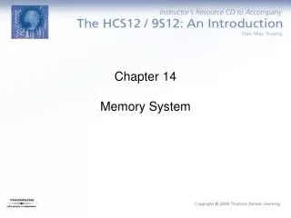
Spacecraft Decontam Heater Power Spacecraft +28V Operational Power Guide Telescope Gain/Red CMDs Operational/Decontam Heaters CCD, SCIP &HI Thermistors SCIP Door Motor Commands Guide Telescope Voltages SCIP/HI Door Encoder Bits MEB 2ndary Voltages HI CEB SCIP CEB GSE Spacecraft 1553 Bus B Spacecraft 1553 Bus A Serial I/F to MEB CEB Power Calibration LEDs GT 2ndary Voltages JTAG Test I/F Chassis Cavity Power Supply Interface Board (PSIB) Power Interface Board (PIB) Space Wire Board (SWIC) House Keeping Board (HKP) RAD750 Processor Board 1553 Board +3.3V, +5V, +/-15V Bus Power cPCI CMD/TLM/”Pass Throughs” Proc Thermistor Secondary Power Items Generated on PIB and Go Out Through HKP I/O Items Come in Through PIB I/O & Get Routed to HKP * SEB Is Single String SEB Block Diagram
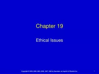
Device History – U37 • Resident in FMA unit - LDC0249 – problem first arose April 2004 • APR 2004: • FMA has data read out issue on all bits with EEPROM during lab testing. Isolated to U37 (LDC 0249). Board inspected & device replaced. Functioned properly thereafter. No other statistics are known. • JUN 2004: • U37 sent to Austin Semiconductor for testing in their in-house screening test fixture • U37 is deemed non-functional. Several leads have continuity issues. Parts sent back to NRL. • JUL 2004: • Failure analysis performed on U37 by OSC at Dulles facility (bond pull test performed per MIL-STD-883B, with pass/fail criteria per method 2011.7, paragraph 3.2, and a SEM performed per MIL-STD-883B, with pass/fail criteria per method 2018 paragraph 3.7.2) • Failed gross leak test – seal voids were found – many leads corroded – see next slide • Analysis shows internal contamination contains Chlorine – this would be found in commonly used PWB cleaning agents/detergents. During cleaning the detergent penetrated the voids • Parts traceability paperwork reviewed – all required screening was performed on our devices. Don’t know how this part got through • This device taken out of intermittent signal investigation since problem was manufacturing/quality issue • All EEPROM devices installed on boards were visually inspected to ensure no other parts had a similar flaw
U37 Failure Analysis Results Void Green/white residue contained corrosive element chlorine
Device History – U25 • Resident in FMA unit - LDC0208 – problem first arose May 2004 • MAY-JUNE 2004: • FMA has boot issues during TVAC testing. Insufficient insight into RAD750 operations in TVAC chamber to debug – completed cycles. No temperature relationship found to exist however. • JUNE 2004: • Post-TVAC FMA debug testing of FSW booting performed. Problem is isolated to 2 bits of a specific page on U25. Problem intermittent, identical to FMB U32 problem • Extensive testing performed: • Special unique patterns written in order to try to isolate all failing bits and read back during 24/7 testing for days. No failures. [Didn’t realize problem would go away once we wrote to the memory devices] • Put FMA 1553 card on extender to assess the signals on the EEPROMs for noise, glitches, etc during normal operations as well as power up/down • Everything nominal • Attempted to recreate TVAC scenarios during test – ran for several days without read back failure • Wrote all zeroes (believed to be best to use in detecting weak writes) to both lower and upper banks of EEPROM on FMA, using the violated timing on page writes of 8ms, instead of the required 10ms, in an attempt to simulate a “weak write” • Ran looping read back tests for several days – no failures • Carefully used freeze spray on U25 device to see if being cold would cause a failure since the issue started at cold during TVAC – no read back failures created by this • Loaded special test pattern recommended by Aerospace white paper [1] and ran thermal tests (-23C to +47C) but could not get read back failures. Several hours of soak, run over many days • Once device was written we could not recreate the page failure • Device replaced on flight board and recommendations in summary implemented
Device History – U32 • Resident in FMB unit - LDC0249 – problem first arose June 2004 • JUNE 2004: • FMB has an intermittent read issue with EEPROM during lab testing. Isolated to a specific page of U32 (LDC 0249). Board sent to FL for debug. • FMB-1553 board testing in FL – scope traces taken showing oscillatory nature of certain EEPROM data outputs on U32 during read cycle. Intermittent nature of problem due to this oscillation (see Greg’s charts) • FMB board received at OSC for inspection/cleaning. Nothing found so U32 was replaced. No failures afterwards. • U32 device sent to Austin Semiconductor for testing in their in-house screening test fixture • U32 was tested successfully and was deemed w/in specs. Traces were taken to simulate our chip access timing. Suggestion made to change the relationship of OE* to CS* to avoid the output switching glitch visible on data outputs for brief period of time. We were not operating the part inconsistent w/ the data sheet, but our timing was thought early on to possibly be allowing/exacerbating the ringing • Note: this part Was Re-Written Prior To Removal & shipping to Austin, during debug testing • Performed investigatory tests on FMB chassis by modifying both the page and word write time required by the EEPROM. Sometimes write was successful, sometimes only every other page would be written, sometimes certain bytes were skipped, depending on what you altered and how far from the required time you had deviated. • Numerous power on/off cycles performed while monitoring the EEPROM Reset and Write lines to monitor for any glitches. Nothing out of spec found. • JULY 2004: • U32 Installed on unused GLAST board for continued testing • Voltage Tests Were Conducted To See If Problem Could Be Recreated With Lower Vcc Voltage • Could Not Recreate The Page Failure
Additional Investigations • Found errata sheets/application notes on Maxwell’s site [2] related to these devices stating a bit flip/intermittent problem had been seen by a few users. Hitachi’s answers to questions posed by user’s are sketchy at best. In all cases the problem was resolved by re-writing and/or mapping around the problematic area • Had telecon with Dr. Doug Sheldon, JPL parts engineer somewhat familiar with MER issues, but EEPROM in general. He sent 2 JPL internal white papers and recommended how they handled the problems they had with these devices: 1) use of the chip’s internal “software protection mode” which ensures the charge pump is good and ready for a write cycle, 2) perform many write cycles (500) to avoid “weak writes”, 3) use of redundant code locations – identical copies of code stored in multiple memory areas spanning unique devices • Received email &voicemail from Yuan Chen, JPL parts engineer associated with MER and other programs. She recommends what they did to handle their problems with these devices: 1) redundancy of code – code stored in multiple locations, 2) the use of EDAC, 3) an “on-board” screening of the devices by reading from them 1000-2000 times (note: the overnight EEPROM read tests we have been looping on results in the EEPROMs having been read 10’s of thousands of times, so we are exceeding this recommendation), and 4) map around any parts that have had issues. • Additional information from her white paper [3]: They determined that “weak cells” were their root cause, which they believe are caused by either process induced defects or poor programming. They did a lot of testing on data retention, and modified the charge pump voltage to simulate weak cells for study. They performed diagnostic write/read cycles to emulate weak cells and demonstrated that weak cells can fail earlier than a properly programmed cell. • Had phone discussion with Aerospace white paper “Experiences in Qualifying a Commercial MNOS EEPROM for Space” author, Elliot King [1] • An intermittent failure was found with 2 devices during the testing being performed for qualifying EEPROMs. In 1 case the failure resolved itself after a couple of hours, in the other case it lasted 2 days then resolved itself. They determined the failure was sensitive to the device power supply, consistently failing at less than 5.00V. It was only specific addresses in the part that failed not all. A screening plan was generated to weed out such early failing parts. One of the criteria important in forcing a failure they found was the pattern programmed into the EEPROMs and the order in which you read it out. We have attempted to simulate this pattern in the patterns being mentioned above as used during our overnight read tests. • Mr. King stated that Hitachi was not forthcoming in helping them resolve this problem. • He stated that the oscillations they saw on the outputs always died out on their own, given sufficient time, and that one of their resolutions was to extend their Read time so that the sampling would occur after the oscillation had damped out • Additional details about the intermittent problem they saw was that only a subset of addresses failed in the device (similar to our page issues) and that the oscillations “suggest that there may be an occasional combination of degraded memory transistor and sense amplifier that produces an instability of the overall data readout behavior.” • Through Austin we attempted to get internal die connectivity/schematic and other detailed device information to attempt to determine root cause. Hitachi was unwilling to provide documentation or a POC to Austin
Findings Summary • Our EEPROM intermittent problems were related to an oscillatory readout problem contained within a page of the device • Root cause of this oscillation never determined • A data value of “0” always failed to a “1” • We ran tests to try to determine a root cause or contributing factor but no problems found: • Temperature: • Initial failures ran the gamut – failures occurred at hot, cold and ambient conditions • Temperature cycling performed and cold spray used to try to re-create the problem to no avail • POR Operations: • Numerous on/off cycles performed - could not recreate the problem • Vcc: • Configured special tests to lower Vcc - could not recreate the problem • Write timing: • Performed many special write cycles violating various combinations of page/word write timing and could not recreate the problem • This problem spans more than one LDC – not LDC related • Note: our parts as procured to SMD part # did have the data retention bake screen performed 100% • Once the intermittent problem occurs, writing to the device “resolves” the problem for TBD days/months/years
NRL Final Recommendations/Plan Implemented • We reviewed many industry findings/recommendations. We applied that information to our findings and generated this list of recommendations to follow internally. Not all of these could be applied to the SECCHI design given the maturity of the hardware at the time • NRL Recommendations when utilizing EEPROM: • Ensure that the CS* to OE* timing on the devices is such that no glitches are present on the data output pins when the outputs are switching and the part is enabled (make sure CS* is asserted sufficiently long enough before OE* is asserted so that this glitch does not get through) ^ • If flight parts are already resident on a board, perform an on-board screening process which involves writing all zeroes to the memory and reading it back and verifying the data on the order of one to two thousand times ^ • Add something like this to device screening at vendor site before delivery in future • Have the capability to map around bad areas of memory • Extend the READ cycle as long as possible, as some saw the oscillatory nature of this problem decay, allowing for the completion of a successful READ if it was sufficiently delayed ^ • Utilize the software protection mode feature of the EEPROM device • Have EDAC protection on the code in EEPROM ^ (SECCHI has SECDED which won’t help w/ a page problem) • Have redundancy in the code in EEPROM – multiple copies spread over the memory addresses, and over unique physical devices/pages ^ • Write more than once when “loading” critical code to EEPROM to ensure strong cumulative charge in cell ^ • Modularize flight software so that code can be more easily re-loaded on-orbit if a problem is determined ^ • Perform a periodic check sum on the EEPROM code, downlink that checksum, and if during the comparison on the ground any problems are found, re-load the effected/corrupt portion of memory ^
References • [1] “Experiences in Qualifying a Commercial MNOS EEPROM for Space”, E.E. King, R.C. Lacoe, G. Eng, and M.S. Leung, The Aerospace Corporation, 2350 E. El Segundo Blvd., (310)336-7898, everett.e.king@aero.org • [2] “1 Mb EEPROM Single Bit Errors” and “Hitachi 1 Mb EEPROM – Hitachi Die HN58C1001”, Maxwell Technologies Application Note, www.maxwell.com • [3] “EEPROM Bit Failure Investigation”, Yuan Chen, Rich Kemski, Leif Scheick, Frank Stott, Duc Nguyen, Tien Nguyen, Richard Bennett, Ken Erickson, Jet Propulsion Laboratory, California Institute of Technology, 4800 Oak Grove Drive, Pasadena, CA 91109