Download
1 / 3
30 likes | 89 Vues
Performance Characteristics of a Spin-FET Paul Thibado DMR-0405036. University of Arkansas, Fayetteville.

E N D
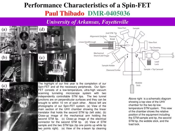
Performance Characteristics of a Spin-FET Paul Thibado DMR-0405036 University of Arkansas, Fayetteville The highlight of our first year is the completion of our Spin-FET and all the necessary peripherals. Our Spin-FET consists of a low-temperature, ultra-high vacuum scanning tunneling microscope system with two independently controllable STM tips. The two tunnel junctions are on perpendicular surfaces and they can be brought to within 10 nm of each other. Above left are photographs of our Spin-FET system. (a) View of the main section of the UHV chamber showing the linear translator that holds the second STM tip (left side). (b) Close-up image of the mechanical arm holding the second STM tip. (c) Close-up image of the electrical connector for the second STM tip. (d) View of STM sample and the two STM tips (tip one points up while tip two points right). (e) View of the e-beam tip cleaning facility. Above right is a schematic diagram showing a top view of the UHV chamber for the two-tip low-temperature STM system. This view of the chamber shows the relative position of the equipment including the STM sample and tip, the second STM tip, the wobble stick, and the load lock.
Performance Characteristics of a Spin-FET Paul Thibado DMR-0405036 University of Arkansas, Fayetteville Above left are STM images taken with STM tip one detecting electrons from the sample and STM tip two injecting the electrons. These images where acquired with normal metal tungsten tips so we will not observe spin polarization effects. These constant current STM images are of HOPG using a set point 1 nA, side tip at a bias of -3V (injecting electrons) and the underneath tip at +3 volts (detecting electrons) and sample is at ground. (a) A 500 nm by 500 nm image with a vertical scale of 0.5 nm. (b) A 100 nm by 100 nm image with a vertical scale of 0.5 nm. (c) A 5 nm by 5 nm image showing atomic resolution. Schematic diagram of the two tips and sample geometry for the STM head. This forms the core elements of the Spin-FET. This is a side view showing the main STM tip comes from the bottom to image the sample (the is the drain), while the second STM tip comes from the left side to image the sample on a perpendicular surface (source). The sample is the channel and can be separately biased.
Performance Characteristics of a Spin-FET Paul Thibado DMR-0405036 University of Arkansas, Fayetteville Working with Girls Scouts and Boy Scouts The P.I. of this project periodically invites girl scouts and boy scouts to visit the lab and perform multiple hands on tasks. This includes building atomic structural models, spot welding, removing air from a small chamber causing a marshmallow to expand, and observing several liquid nitrogen demonstrations. The scouts are told about the critical need for Americans to go into physics, especially women. Scouts are a great group of kids already organized with scout leaders and they get a science patch for their efforts.