Download
1 / 75
1k likes | 1.8k Vues
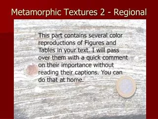
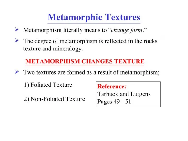
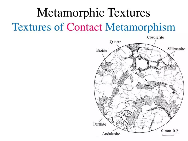
Metamorphic Textures Textures of Contact Metamorphism. Sandstone texture. Quartzite texture. Metamorphic Textures Textures of Regional Metamorphism. Dynamothermal (crystallization under dynamic conditions) Orogeny- long-term mountain-building May comprise several Tectonic Events

E N D
Sandstone texture Quartzite texture
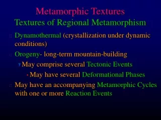
Metamorphic TexturesTextures of Regional Metamorphism • Dynamothermal (crystallization under dynamic conditions) • Orogeny- long-term mountain-building • May comprise several Tectonic Events • May have several Deformational Phases • May have an accompanying Metamorphic Cycles with one or more Reaction Events
Metamorphic TexturesTextures of Regional Metamorphism • Tectonite- a deformed rock with a texture that records the deformation • Fabric- the complete spatial and geometric configuration of textural elements • Foliation- planar textural element • Lineation- linear textural element • Lattice Preferred Orientation (LPO) • Dimensional Preferred Orientation (DPO)
Progressive syntectonic metamorphism of a volcanic graywacke, New Zealand. From Best (1982). Igneous and Metamorphic Petrology. W. H. Freeman. San Francisco.
Progressive syntectonic metamorphism of a volcanic graywacke, New Zealand. From Best (1982). Igneous and Metamorphic Petrology. W. H. Freeman. San Francisco.
Progressive syntectonic metamorphism of a volcanic graywacke, New Zealand. From Best (1982). Igneous and Metamorphic Petrology. W. H. Freeman. San Francisco.
Progressive syntectonic metamorphism of a volcanic graywacke, New Zealand. From Best (1982). Igneous and Metamorphic Petrology. W. H. Freeman. San Francisco.
Fig 23.21 Types of foliations a. Compositional layering b. Preferred orientation of platy minerals c. Shape of deformed grains d. Grain size variation e. Preferred orientation of platy minerals in a matrix without preferred orientation f. Preferred orientation of lenticular mineral aggregates g. Preferred orientation of fractures h. Combinations of the above Figure 23.21.Types of fabric elements that may define a foliation. From Turner and Weiss (1963) and Passchier and Trouw (1996).
Figure 23.22.A morphological (non-genetic) classification of foliations. After Powell (1979) Tectonophys., 58, 21-34; Borradaile et al. (1982) Atlas of Deformational and Metamorphic Rock Fabrics. Springer-Verlag; and Passchier and Trouw (1996) Microtectonics. Springer-Verlag.
a b Figure 23.23.Continuous schistosity developed by dynamic recrystallization of biotite, muscovite, and quartz. a. Plane-polarized light, width of field 1 mm. b. Crossed-polars, width of field 2 mm. Although there is a definite foliation in both samples, the minerals are entirely strain-free.
Progressive development (a c) of a crenulation cleavage for both asymmetric (top) and symmetric (bottom) situations. From Spry (1969) Metamorphic Textures. Pergamon. Oxford.
Figure 23.24a.Symmetrical crenulation cleavages in amphibole-quartz-rich schist. Note concentration of quartz in hinge areas. From Borradaile et al. (1982) Atlas of Deformational and Metamorphic Rock Fabrics. Springer-Verlag.
Figure 23.24b.Asymmetric crenulation cleavages in mica-quartz-rich schist. Note horizontal compositional layering (relict bedding) and preferential dissolution of quartz from one limb of the folds. From Borradaile et al. (1982) Atlas of Deformational and Metamorphic Rock Fabrics. Springer-Verlag.
Figure 23.25.Stages in the development of crenulation cleavage as a function of temperature and intensity of the second deformation. From Passchier and Trouw (1996) Microtectonics. Springer-Verlag. Development of S2 micas depends upon T and the intensity of the second deformation
Types of lineations a. Preferred orientation of elongated mineral aggregates b. Preferred orientation of elongate minerals c. Lineation defined by platy minerals d. Fold axes (especially of crenulations) e. Intersecting planar elements. Figure 23.26.Types of fabric elements that define a lineation. From Turner and Weiss (1963) Structural Analysis of Metamorphic Tectonites. McGraw Hill.
Figure 23.27.Proposed mechanisms for the development of foliations. After Passchier and Trouw (1996) Microtectonics. Springer-Verlag.
Figure 23.28.Development of foliation by simple shear and pure shear (flattening). After Passchier and Trouw (1996) Microtectonics. Springer-Verlag.
Development of an axial-planar cleavage in folded metasediments. Circular images are microscopic views showing that the axial-planar cleavage is a crenulation cleavage, and is developed preferentially in the micaceous layers. From Gilluly, Waters and Woodford (1959) Principles of Geology, W.H. Freeman; and Best (1982). Igneous and Metamorphic Petrology. W. H. Freeman. San Francisco.
Diagram showing that structural and fabric elements are generally consistent in style and orientation at all scales. From Best (1982). Igneous and Metamorphic Petrology. W. H. Freeman. San Francisco.
Pre-kinematic crystals • Bent crystal with undulose extinction • Foliation wrapped around a porphyroblast • Pressure shadow or fringe • Kink bands or folds • Microboudinage • Deformation twins Figure 23.34.Typical textures of pre-kinematic crystals. From Spry (1969) Metamorphic Textures. Pergamon. Oxford.
Post-kinematic crystals a. Helicitic folds b. Randomly oriented crystals c. Polygonal arcs d. Chiastolite e. Late, inclusion-free rim on a poikiloblast (?) f. Random aggregate pseudomorph Figure 23.35.Typical textures of post-kinematic crystals. From Spry (1969) Metamorphic Textures. Pergamon. Oxford.
Syn-kinematic crystals Paracrystalline microboudinage Spiral Porphyroblast Figure 23.38.Traditional interpretation of spiral Si train in which a porphyroblast is rotated by shear as it grows. From Spry (1969) Metamorphic Textures. Pergamon. Oxford. Figure 23.36.Syn-crystallization micro-boudinage. Syn-kinematic crystal growth can be demonstrated by the color zoning that grows and progressively fills the gap between the separating fragments. After Misch (1969) Amer. J. Sci., 267, 43.63.
Syn-kinematic crystals Figure 23.38.Spiral Si train in garnet, Connemara, Ireland. Magnification ~20X. From Yardley et al. (1990) Atlas of Metamorphic Rocks and their Textures. Longmans.
Syn-kinematic crystals Figure 23.40.Non-uniform distribution of shear strain as proposed by Bell et al. (1986) J. Metam. Geol., 4, 37-67. Blank areas represent high shear strain and colored areas are low-strain. Lines represent initially horizontal inert markers (S1). Note example of porphyroblast growing preferentially in low-strain regions.
Syn-kinematic crystals Figure 23.38.“Snowball garnet” with highly rotated spiral Si. Porphyroblast is ~ 5 mm in diameter. From Yardley et al. (1990) Atlas of Metamorphic Rocks and their Textures. Longmans.
Figure 23.37.Si characteristics of clearly pre-, syn-, and post-kinematic crystals as proposed by Zwart (1962). a. Progressively flattened Si from core to rim. b. Progressively more intense folding of Si from core to rim. c. Spiraled Si due to rotation of the matrix or the porphyroblast during growth. After Zwart (1962) Geol. Rundschau, 52, 38-65.
Analysis of Deformed Rocks • Deformational events: D1 D2 D3 … • Metamorphic events: M1 M2 M3 … • Foliations: So S1 S2 S3 … • Lineations: Lo L1 L2 L3 … • Plot on a metamorphism-deformation-time plot showing the crystallization of each mineral
Analysis of Deformed Rocks Figure 23.42. (left) Asymmetric crenulation cleavage (S2) developed over S1 cleavage. S2 is folded, as can be seen in the dark sub-vertical S2 bands. Field width ~ 2 mm. Right: sequential analysis of the development of the textures. From Passchier and Trouw (1996) Microtectonics. Springer-Verlag.
Analysis of Deformed Rocks Figure 23.43.Graphical analysis of the relationships between deformation (D), metamorphism (M), mineral growth, and textures in the rock illustrated in Figure 23.42. Winter (2010) An Introduction to Igneous and Metamorphic Petrology. Prentice Hall.
Figure 23.45.Graphical analysis of the relationships between deformation (D), metamorphism (M), mineral growth, and textures in the rock illustrated in Figure 23.44. Winter (2010) An Introduction to Igneous and Metamorphic Petrology. Prentice Hall. Analysis of Deformed Rocks Figure 23.44.Composite sketch of some common textures in Pikikiruna Schist, N.Z. Garnet diameter is ~ 1.5 mm. From Shelley (1993) Igneous and Metamorphic Rocks Under the Microscope. Chapman and Hall.
Figure 23.47.Graphical analysis of the relationships between deformation (D), metamorphism (M), mineral growth, and textures in the rock illustrated in Figure 23.46. Winter (2010) An Introduction to Igneous and Metamorphic Petrology. Prentice Hall. Figure 23.46.Textures in a hypothetical andalusite porphyryoblast-mica schist. After Bard (1986) Microtextures of Igneous and Metamorphic Rocks. Reidel. Dordrecht.
Figure 23.48a.Interpreted sequential development of a polymetamorphic rock. From Spry (1969) Metamorphic Textures. Pergamon. Oxford.
Figure 23.48b.Interpreted sequential development of a polymetamorphic rock. From Spry (1969) Metamorphic Textures. Pergamon. Oxford.
Figure 23.48c.Interpreted sequential development of a polymetamorphic rock. From Spry (1969) Metamorphic Textures. Pergamon. Oxford.
Post-kinematic: Si is identical to and continuous with Se Pre-kinematic: Porphyroblasts are post-S2. Si is inherited from an earlier deformation. Se is compressed about the porphyroblast in (c) and a pressure shadow develops. Syn-kinematic: Rotational porphyroblasts in which Si is continuous with Se suggesting that deformation did not outlast porphyroblast growth. From Yardley (1989) An Introduction to Metamorphic Petrology. Longman.
Deformation may not be of the same style or even coeval throughout an orogen Stage I: D1 in forearc (A) migrates away from the arc over time. Area (B) may have some deformation associated with pluton emplacement, area (C) has no deformation at all Figure 23.49.Hypothetical development of an orogenic belt involving development and eventual accretion of a volcanic island arc terrane. After Passchier and Trouw (1996) Microtectonics. Springer-Verlag.
Deformation may not be of the same style or even coeval throughout an orogen Stage II: D2 overprints D1 in forearc (A) in the form of sub-horizontal folding and back-thrusting as pushed against arc crust. Area (C) begins new subduction zone with thrusting and folding migrating toward trench. Figure 23.49.Hypothetical development of an orogenic belt involving development and eventual accretion of a volcanic island arc terrane. After Passchier and Trouw (1996) Microtectonics. Springer-Verlag.
Deformation may not be of the same style or even coeval throughout an orogen Stage III: Accretion deforms whole package. More resistant arc crust gets a D1 event. D2 overprints D1 in forearc (A) and in pluton-emplacement structures in (B). Area (C) in the suture zone gets D3 overprinting D2 recumbent folds on D1 foliations. Figure 23.49.Hypothetical development of an orogenic belt involving development and eventual accretion of a volcanic island arc terrane. After Passchier and Trouw (1996) Microtectonics. Springer-Verlag.
Deformation may not be of the same style or even coeval throughout an orogen The orogen as it may now appear following uplift and erosion. Figure 23.49.Hypothetical development of an orogenic belt involving development and eventual accretion of a volcanic island arc terrane. After Passchier and Trouw (1996) Microtectonics. Springer-Verlag.
Figure 23.53.Reaction rims and coronas. From Passchier and Trouw (1996) Microtectonics. Springer-Verlag.
Figure 23.54.Portion of a multiple coronite developed as concentric rims due to reaction at what was initially the contact between an olivine megacryst and surrounding plagioclase in anorthosites of the upper Jotun Nappe, W. Norway. From Griffen (1971) J. Petrol., 12, 219-243.
Photomicrograph of multiple reaction rims between olivine (green, left) and plagioclase (right).
Coronites in outcrop. Cores of orthopyroxene (brown) with successive rims of clinopyroxene (dark green) and garnet (red) in an anorthositic matrix. Austrheim, Norway.
Application of radiometric dating techniques for minute samples in textural context Determine ages of mineral growth and separate deformational/metamorphic events. Thermal ionization mass spectrometry (TIMS): ionization of (sub-nanogram) samples on a filament and mass spectrometry of the ionized isotopes. Tiny drill can “microsample” pieces of single mineral grains a few tens of mm across for analysis. Mineral samples can thus be observed in thin section and microsampled from specific textural situations. Laser-ablation inductively-coupled plasma mass spectrometry (LA-ICPMS). A high-power laser ablates a sample in situ and particles are fed into a mass spectrometer. Ultraviolet (UV) laser ablation has a spatial resolution 10mm, so it can determine ages within zoned minerals and inclusions in porphyroblasts as they are observed microscopically. Ion microprobe (IMP, SHRIMP), also called secondary-ion mass spectrometry (SIMS). Uses an ion beam (typically Cs or O) to sputter ions from a sample surface while observed in thin section and feed them into a mass spectrometer. Resolutions down to 30mm are possible. Electron microprobe (EMP) Some new probes are now optimized for trace element analysis and geochronology. Textural Geochronology
Christensen et al. (1989) used TIMS to measure 87Sr/86Sr in single garnets from SE Vermont. 87Rb in K-rich matrix minerals (such as biotite) → 87Sr, which was then incorporated into growing garnet (which accepts Ca, hence Sr, but not Rb). Garnets grew during the Acadian orogeny (~380 Ma). Determined core and rim ages for three garnets → average duration of garnet growth to be 10.54.2 Ma. Then, by measuring garnet radii, they calculated the average growth rate: 1.4 mm/Ma. One garnet with spiral inclusions also yielded a rotational shear strain rate of 7.6x10⁻⁷ a-1 (0.76 per Ma). Textural Geochronology Examples
Simpson et al. (2000) TIMS isotopic ratios on monazite separates, Everest region of Nepal. Older euhedral monazite oriented sillimanite inclusions parallel to S1 in the matrix: growth either syn- or post-sillimanite and post S1 (32.20.4 Ma). Later lower-pressure metamorphism → cordierite and irregular-shaped monazite (yielded 22.70.2 Ma). The Everest granite dated at 21.3-20.5 Ma. Place far better constraints than earlier traditional works on post-collision metamorphism, with early Barrovian metamorphism peaking at 32 Ma and a second low-P event at 22.7 Ma (post-orogenic collapse?). Granites (probably related to collapse) emplaced at 20-21 Ma. Textural Geochronology Examples Figure 23.55 Backscattered SEM images of textural relationships of monazites from the Everest region of Nepal. a. Well-developed M1 monazite enveloping sillimanite inclusions aligned sub-parallel to external S1 foliation. b. Nearly euhedral M1 monazite in the same sample surrounded by armoring plagioclase. c. Irregularly shaped M2 monazite in a nearby sample. From Simpson et al. (2000).
Müller et al. (2000) microsampled carbonate and quartz-chlorite from incrementally-developed strain fringes of s-type mantles on pyrite porphyroclasts from a shear zone in northern Pyrenees. Fringes developed during two distinct phases of shear (D2 and D3) following an earlier period of crustal shortening (D1 - which created a foliation preserved as straight inclusion trails within the pyrites). Pyrites thus grew as post-D1 porphyroblasts, but were deformed during D2 and D3. Textural Geochronology Examples
Notice that successive increments develop between the porphyroclast and receding earlier fringe, not at the ends of the fringe tails. Figure 23.56a. Broken pyrite porphyroblast with sigmoidal fibrous carbonate-quartz-chlorite strain fringe and kinematic reconstruction above. Area generated during D2 and D3 events are outlined with dashed lines in photomicrograph (arrows indicate Rb-Sr ages) and shaded in the reconstruction (with arrows indicating the direction of fiber growth). b. Photomicrograph of an unbroken pyrite porphyroblast and strain fringe with outlined growth zones and Rb-Sr ages. After Müller et al. (2000).