Download
1 / 22
220 likes | 225 Vues
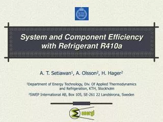
System and Component Efficiency with Refrigerant R410a. A. T. Setiawan 1 , A. Olsson 2 , H. Hager 2 1 Department of Energy Technology, Div. Of Applied Thermodynamics and Refrigeration, KTH, Stockholm 2 SWEP International AB, Box 105, SE-261 22 Landskrona, Sweden. Overview. Properties of R410A

E N D
System and Component Efficiency with Refrigerant R410a A. T. Setiawan1, A. Olsson2, H. Hager2 1Department of Energy Technology, Div. Of Applied Thermodynamics and Refrigeration, KTH, Stockholm 2SWEP International AB, Box 105, SE-261 22 Landskrona, Sweden
Overview • Properties of R410A • Comparison with other common refrigerants • System characteristics • Experimental test facility • Experimental heat transfer results • Comparison to other data and other refrigerants Div. of Applied Thermodynamics and Refrigeration Department of Energy Technology Royal Institute of Technology, Stockholm
R410aProperties • 50/50 mixture of R32/R125 (CH2F2 – C2HF5) • Glide : Less than 0,1°C (azeotropic) • Comparably high pressure (15 Bars at Tamb) • ODP : 0 % (HFC refrigerant) • GWP : 1730 (compared to CO2) Div. of Applied Thermodynamics and Refrigeration Department of Energy Technology Royal Institute of Technology, Stockholm
R410aVapor Pressure curve Div. of Applied Thermodynamics and Refrigeration Department of Energy Technology Royal Institute of Technology, Stockholm
COP2, comparison of refrigerants (T1=40°C) Div. of Applied Thermodynamics and Refrigeration Department of Energy Technology Royal Institute of Technology, Stockholm
Pressure ratio, comparison of refrigerants (T1=40°C) Div. of Applied Thermodynamics and Refrigeration Department of Energy Technology Royal Institute of Technology, Stockholm
Pro’s Con’s • Low specific volume, lead to smaller piping and other components • No glide (0.1K) • No ODP (Ozone Depleting Potential) • Appropriate for new systems • High pressure, need special components • GWP (Global Warming Potential) • Not appropriate when converting old R22 systems • Low critical temperature (73ºC), limiting the condensation temperature. R410aPro’s and Con’s Div. of Applied Thermodynamics and Refrigeration Department of Energy Technology Royal Institute of Technology, Stockholm
Figures of MeritEvaporation in horizontal tubes Div. of Applied Thermodynamics and Refrigeration Department of Energy Technology Royal Institute of Technology, Stockholm
Figures of Merit Evaporator (examples) Evaporator Pressure Drop Boiling Heat Transfer Div. of Applied Thermodynamics and Refrigeration Department of Energy Technology Royal Institute of Technology, Stockholm
SSP–CBE ModellingRelative CBE size, chiller mode Div. of Applied Thermodynamics and Refrigeration Department of Energy Technology Royal Institute of Technology, Stockholm
SSP–CBE ModellingRelative CBE size, heat pump Div. of Applied Thermodynamics and Refrigeration Department of Energy Technology Royal Institute of Technology, Stockholm
Experimental Test FacilityAvailability of components • Hermetic compressors available (?) up to 150 kW cooling (tandem) • Expansion valve : Limited availability • Copper tubes up to 12 mm, then steel • Sight glass, filter-dryer, valves available • Check valve, oil separator, limited Div. of Applied Thermodynamics and Refrigeration Department of Energy Technology Royal Institute of Technology, Stockholm
Experimental Test FacilityTested heat exchangers • Condenser : • Plate heat exchanger (CBE), 34 plates, 2.0 m2 co-current and counter-current • Evaporator : • Plate heat exchanger (CBE), 34 plates, 2.0 m2 • Plate heat exchanger (CBE), 32 plates, 1.0 m2 both counter-current Div. of Applied Thermodynamics and Refrigeration Department of Energy Technology Royal Institute of Technology, Stockholm
Experimental Test FacilitySchematic view Div. of Applied Thermodynamics and Refrigeration Department of Energy Technology Royal Institute of Technology, Stockholm
Experimental Test FacilityThe Refrigerant loop, schematic Div. of Applied Thermodynamics and Refrigeration Department of Energy Technology Royal Institute of Technology, Stockholm
Evaporator testOperational conditions • Evaporation temp : 2°C • Inlet vapor quality : 20% • DTSuperheat = 4°C • Heat flux range : 8 – 15 kW/m2 • DTBrine = 5°C Div. of Applied Thermodynamics and Refrigeration Department of Energy Technology Royal Institute of Technology, Stockholm
Evaporator testDifferent CBE size Div. of Applied Thermodynamics and Refrigeration Department of Energy Technology Royal Institute of Technology, Stockholm
Condenser testOperational conditions • Condensing temp : 40°C • Compressor discharge temp : 75°C • No subcooling • Heat flux range : 9 – 18 kW/m2 • DTBrine = 5°C Div. of Applied Thermodynamics and Refrigeration Department of Energy Technology Royal Institute of Technology, Stockholm
Condenser testDifferent flow direction Div. of Applied Thermodynamics and Refrigeration Department of Energy Technology Royal Institute of Technology, Stockholm
Evaporator testComparison with literature data Div. of Applied Thermodynamics and Refrigeration Department of Energy Technology Royal Institute of Technology, Stockholm
(R410A) Condenser testComparison with literature data Div. of Applied Thermodynamics and Refrigeration Department of Energy Technology Royal Institute of Technology, Stockholm
Thank you for your attention For more information, please refer to final report. Div. of Applied Thermodynamics and Refrigeration Department of Energy Technology Royal Institute of Technology, Stockholm