Download
1 / 20
200 likes | 308 Vues
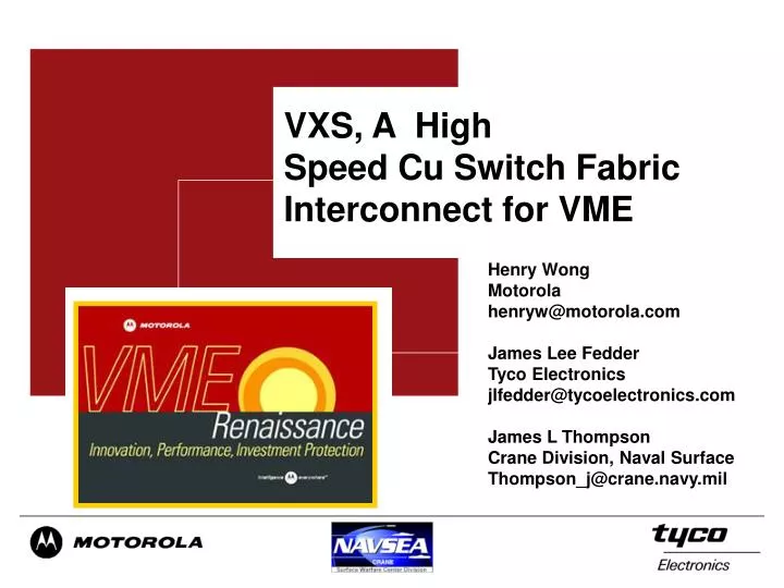
VXS, A High Speed Cu Switch Fabric Interconnect for VME. Henry Wong Motorola henryw@motorola.com James Lee Fedder Tyco Electronics jlfedder@tycoelectronics.com James L Thompson Crane Division, Naval Surface Thompson_j@crane.navy.mil. VME Renaissance. VME is a +20 year old technology.

E N D
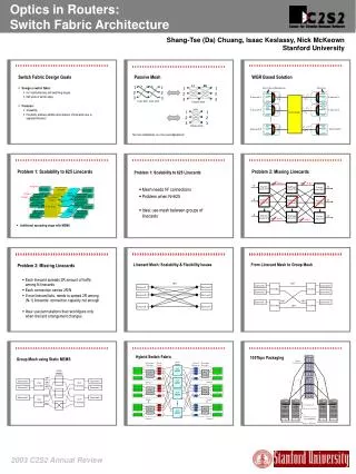
VXS, A High Speed Cu Switch Fabric Interconnect for VME Henry Wong Motorola henryw@motorola.com James Lee Fedder Tyco Electronics jlfedder@tycoelectronics.com James L Thompson Crane Division, Naval Surface Thompson_j@crane.navy.mil
VME Renaissance • VME is a +20 year old technology. • VME Renaissance is an intense period of intellectual activity and technology infusion surrounding VMEbus • Many innovations, including but not limited to • Faster 2eSST parallel bus • Multi-gigabit switched serial interconnects • PCI-X chip to chip interconnect • PCI-X mezzanines • Point to point intra-connects • Point-to-point mezzanines
VMEbus Technology Roadmap Next Gen Fabric ParallelSwitched 2eSST/PCI-XVMEbus • Raceway™ • SKYchannel • HA fabric • Mesh • Optical • 8X speed improvement • Backwards compatible • VITA 1.5 Next Gen VMEbus VME64VMEbus 2eSST/P2P VMEbus PCI-X • Universe II from Tundra • Other proprietary chips • 2eSST VME side • P-P Host side connect • QDR Technology • 64b/133MHz PCI Point-to-PointChip Connect • 64b/66MHz • Proprietary connects also • P/S RapidIO™ • 3GIO • Hypertransport • etc. etc. Next Gen Mezzanine PMC PMCX Point-to-PointMezzanine • PCI Mezzanine Cards • PMC & PrPMC • 64b/66MHz based • PCI-X Mezzanine Cards • PMCX & PrPMCX • 64b/133MHz based • VITA 39 • P/S RapidIO™ • 3GIO • Hypertransport • Infiniband™, etc. etc. • Hot plug • Front Access Next Gen Form 3U/6UEurocard • VITA 34 or other More real estate • More power • More cooling • High availability support • Integrated chassis management • 3U/6U Eurocards • 160 millimeters deep Serial Switched DataPlaneInter-Connect • Ethernet, Fibre Ch • Infiniband™ • Serial RapidIO™ • 3GIO, etc. etc. etc. ControlPlaneInter-Connect • VXS – VMEbus Switched Serial • Adds multi-gigabit per second switched serial links to VME • Via a new P0 connector • Dual star configuration uses one or two switch cards • Multiple link technologies supported by structured specification • Additional power brought onto each card • Plug Fest during 03’ and 04’ MezzanineInter-Connect ChiptoChip Inter-Connect Form Factor 2002 2003 2004 2005-10 2001 Source: Jeff Harris, Motorola
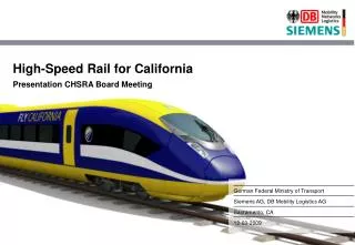
Payload and Switch Boards 160 mm 160 mm User I/O Alignment + Keying A2K2 P1 P5 6U 6U A0K0 Twenty 4X channels P4 P0 P3 P2 Two 4X channels + mgnt A1K1 P2 VME cntrl + mgnt + live insert P1 Power Payload Switch
Interconnect Topologies • VXS is topology agnostic • Only Payload and Switch Board Pin outs defined • Dual star • Mesh • Ring Example Backplane 20 slot dual star
VXS.4Reserved for3GIOLink Technology VXS.9Reserved forOut of BandSystem & ChassisManagement VXS.10Live-Insertion Specification VXS.5StarFabricLink Technology Active Draft Specifications Reserved for future use VSO (VITA Standards Organization) • All work done under VSO (March 2002 to present) • SIG (6 companies) -> Working Group (+20 companies) VXS.0Base SpecificationMechanical, power, etc. VXS.14X InfiniBand Link Technology VXS.24X Serial RapidIOLink Technology VXS.3Reserved for10 Gigabit EthernetLink Technology … Provisional Draft Standards
MultiGig RT-2 Assembly Most Flexible, Most Dense, and Quiet A Solution Revolution for Multi-Gigabit Backplane applications
MultiGig Product Family Overview • Options • Complete integrated solution • Designed to fit within same • envelope as signal modules • Power Connectors 18 A contacts, 2 & 4 lines/module • Guide Modules 8 keys/pin, Positive ESD Contact option • DC Organizer Modules can be organized as monoblocks • Cross Connect Orthogonal Design in Dev.
MultiGig Product Family Overview • Features and Benefits • Mechanically Robust • Pinless Backplane Solution • Bellcore Compliant • 250 cycle durability • Electrically Flexible • Single Ended and Differential lines within a module • PWB’s for Power options available • Length Matching • Skew Control • Options available down to 3% Noise at 50 ps
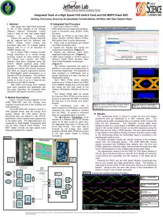
Pr 8 Pr 7 Pr 6 Pr 5 Pr 4 Pr 3 Pr 2 Pr 1 MultiGig RT-2 Differential - Near End Noise Synchronous Noise Multiple aggressors Pair 7 2.9% Pair 8 1.7% Pair 5 3.0% Pair 6 3.1% Pair 3 2.9% Pair 4 2.9% Pair 1 2.7% Pair 2 2.8% Edge rate: 47 ps (20-80%)
Pr 8 Pr 7 Pr 6 Pr 5 Pr 4 Pr 3 Pr 2 Pr 1 MultiGig RT-2 Differential - Far End Noise Synchronous Noise Multiple aggressors Pair 7 1.6% Pair 8 2.7% Pair 5 2.1% Pair 6 2.4% Pair 3 2.6% Pair 4 2.2% Pair 1 3.0% Pair 2 1.0% Edge rate: 47 ps (20-80%)
Physical Test Environment • Two RT2 connectors, a backplane and 2 daughtercards • Backplane thickness designed at 0.200” with common FR4 material • Daughtercard thicknesses designed at 0.125” with common FR4 material • Trace widths designed at 6 mils on backplane and daughtercards • 100 differential pairs on all boards • All connector rows analyzed during the testing • Top and bottom layer via connections included • Top layer via connections designed with and without counterboring
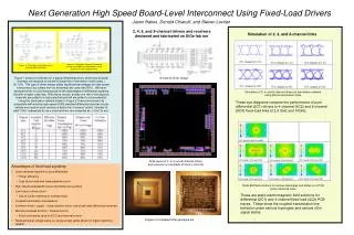
Measured RT2 Eye Pattern (Worst-case trace-to-via connection) • Test Conditions: • 16” FR4 backplane traces • 4” FR4 daughtercard traces • Top layer via connection • No counterboring • 2 7 -1 PRBS • 46.8% Eye Opening Measured RT2 Eye Pattern – 16” Backplane, Top Layer, No Counterbore
10 Gbps Data with Advanced Silicon • Successful recovery of signal • Not possible at 10 Gbps without advanced silicon • Test Conditions • 24” FR4 backplane traces • 4” FR4 daughtercard traces • 6-mil trace widths • Top layer via connection • Counterbored vias • 2 7 -1 PRBS • Advanced Silicon • Successful data recovery • Advanced materials will further improve results.
Environmental Testing (MIL-COTS-Telco ) • Concerns raised about MIL-COTS-Teclo acceptance of edge card connectors • Address gas tight seal concerns • Verifies acceptable operation under vibration • MIL environment • Shock (50g’s), Vibration (15g’s), Humidity (condensing) • Salt fog • Recognized Standards • MIL-STD-1344A (MIL-COTS) • IEC 603.2 (General) • Telcordia GR-1217 (Telco)
Pass/Fail Criteria • Discontinuity • Test Method EIA-367-87 Nanosecond-Event Detection for electrical Connectors. • Contacts were continuously monitored for discontinues of 10 Ohms or greater during Shock and vibration testing. • No Discontinuities were noted. • Low-Signal Level Contact Resistance (LLCR) • 20 mV open circuit, 100 mA short circuit • Insulation Resistance • 500 Volts DC applied for 2 minutes to mated connector • 100 MegOhm minimum allowed
Test Conclusions • Passed MIL-STD-1344A tests for • Humidity, Condensing • Salt Fog • Thermal Shock, -55 to +125 C • Vibration, random 11.95 GRMS • Vibration, simple harmonic motion, 15 gravity units • Shock, half-sine, 11 milliseconds, 50g’s • Passed Telcordia GR1217 • Quality level III (highest)