Download
1 / 24
240 likes | 390 Vues
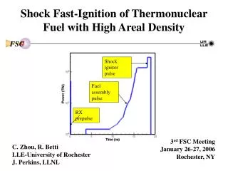
IGNITION OF ALUMINUM PARTICLE CLOUDS BEHIND REFLECTED SHOCK WAVES. Kaushik Balakrishnan 1 , Allen L. Kuhl 2 , John B. Bell 1 , Vincent E. Beckner 1 1 Lawrence Berkeley National Laboratory 2 Lawrence Livermore National laboratory. ICDERS 2011, #329.

E N D
IGNITION OF ALUMINUM PARTICLE CLOUDS BEHIND REFLECTED SHOCK WAVES Kaushik Balakrishnan1, Allen L. Kuhl2, John B. Bell1, Vincent E. Beckner1 1 Lawrence Berkeley National Laboratory 2 Lawrence Livermore National laboratory ICDERS 2011, #329 Supported by U.S. Department of Energy and Defense Threat Reduction Agency
INTRODUCTION • Al combustion is of interest • High energy content (7.4 Kcal/g) • Al added to explosives and propellants • Simulation of Al dispersion/combustion is challenging in explosion/shock flow fields • Ignition/burn models • Turbulent flow field • Two-phase modeling • Use of experimental data in models • Empirical ignition model
IGNITION BY REFLECTED SHOCK WAVE • Boiko et al.’s experiments (Russia) • Krier/Glumac experiments (Univ. Illinois)
IGNITION BY REFLECTED SHOCK WAVE wake RM • Wake convected into the particle cloud • Reflected shock interaction with particle cloud: Richtmyer-Meshkov instability • Clockwise/counter-clockwise vorticity • Particle cloud convolutes
FORMULATION GAS PHASE CONTINUITY MOMENTUM ENERGY SPECIES PARTICLE PHASE CONTINUITY MOMENTUM ENERGY &
FORMULATION: THERMODYNAMICS • Equation of state • Le Chatelier diagram (Kuhl, 2006) • Thermodynamic states computed using CHEETAH code • Thermodynamic equilibrium assumed for reactants and products • Quadratic curve-fits • uk(T) = akT2 + bkT + ck • K =fuel, oxidizer or products
NUMERICAL METHODS - AMR • GAS PHASE: Higher-order Godunov method of Colella & Glaz, 1985; Bell et al., 1989 • PARTICLE PHASE: Godunov method of Collins et al., 1994 • ADAPTIVE MESH REFINEMENT (AMR) of Bell et al., 1989 • IMPLICIT LARGE-EDDY SIMULATION (ILES) • MASSIVELY PARALLEL SIMULATIONS (~1024 processors)
EMPIRICAL IGNITION MODEL • INDUCTION PATAMETER f(x,t) • Experiments of Boiko et al., 1989 • Spherical Al particles and flakes • Gas temperature: 1700-2100 K • 1: Al spheres; 2: Al-Fe spheres; 3: Al flakes • A = 6.25x10⁷ flakes; A = 4x10⁷ spheres • E = 60 Kcal/mol
EMPIRICAL IGNITION MODEL • Kuhl & Boiko curve-fit, ICT 41, 2010 • Tg < 2000 K • Roberts et al., 1993 experiment • Tg > 2000 K
EMPIRICAL IGNITION MODEL • Boiko et al. experiments, 1989 reveal a cutoff particle cloud concentration is required to sustain burning μc(); μc()= ; b = 20 g/m3 • Gurevich et al. experiments, 1970 • Tign function of dp, λ and Cox • ∙∙exp(-0.85)
SUMMARY: IGNITION MODEL • Additional equation for induction parameter, f(x,t) based on experimental data for ignition time delay • Particle size and gas temperature • Tign from Gurevich’s experiments • Accounts for particle size, oxidizer concentration and gas thermal conductivity • DEFINE:Ignition occurs if f > 1 and Tsolid > Tign • Cloud concentration included • μc() • Khasainov’s model used in the present study • Zhang’s model can be explored in future Initial: f = 0 Pre-ignition: 0<f<1 Ignition: f>1
SIMULATION CONFIGURATION • Spherical Al particle cloud in shock tube; air everywhere • 3.2m x 0.4m x 0.4m; left: inflow; walls everywhere else • Shock wave initialized at x = 0.5m; 0.1 bar and 293 K for x>0.5m • 5 cm particle cloud (4-6 µm Al flakes) injected at x=2.75 m at 2.25 msec • 512x64x64 with 3 levels of refinement (ratio=2); ∆x3≈0.78 mm
DIFFERENT SIMULATION CASES EFFECT OF INITIAL CLOUD DENSITY AND SHOCK MACH NUMBER
RESULTS: log(ρs) • M = 4; ρs = 200 g/m3 • M = 4; ρs = 50 g/m3
VORTICITY: M = 4; ρs = 200 g/m3 2.83 ms 3.52 ms 4.28 ms 5.37 ms • Vorticity due to wake: 1.2x10⁵ sec-1 • Due to reflected shock: 4x10⁴ sec-1 • Vorticity dependent on ρs and M
MASS OF Al BURNED • Burning trend depends on ρs • 90% Al by mass burns • Present ignition model accounts for ρs • Wake-induced convolution/elongation of cloud for higher ρs • Increases surface area of cloud; hence more burning
BURNING REGIONS Tg 200 g/m3 50 g/m3 Yair
EFFECT OF M (ρs = 100 g/m3) • Higher M results in higher Tg behind reflected shock • Ignition occurs earlier • More Al by mass burns
MASS WEIGHTED f • fMW = • Quantifies global cloud burning trend • ρs: peak and subsequent decay dependent on ρs • M: Earlier ignition for higher M • SIMILAR TO EXPERIMENTAL PHOTO-DIODE SIGNALS • ~250 µs burn time for 4-6 µm Al particles
CONCLUSIONS • A new empirical Al ignition model is proposed • Ignition time based on Boiko et al.’s experiments • Ignition temperature based on Gurevich et al.’s experiments • Cloud concentration effect • RESULTS • ~90% Al (by mass) burns • Cloud density and M have profound effect • Mass-weighted f introduced
RESULTS FROM A COMPANION PAPER • Shock Dispersed Fuel (SDF) charges • Investigate Al burning, mixing, vorticity, dissociation and ionization effects