Download
1 / 19
190 likes | 198 Vues
T. Straumann M. Cecere E. Medvedko P. Krejcik. Stripline BPM Processors. Requirements/Engineering Constraints Status Current Frontend Design Timeline for next 12 months. Overview. Objective. High precision/resolution BPM Electronics 5um resolution (R ~ 12mm) drift < 5um/h

E N D
T. Straumann M. Cecere E. Medvedko P. Krejcik Stripline BPM Processors
Requirements/Engineering Constraints Status Current Frontend Design Timeline for next 12 months Overview
Objective • High precision/resolution BPM Electronics • 5um resolution (R ~ 12mm) • drift < 5um/h • low bunch charge: 0.2..1nC • Stripline sensitivity: V = (a-b)/(a+b) = 2 r / R • dynamic range > 60dB + 20dB
Engineering Constraints • SNR expressed as position noise (LINAC Stripline; 150MHz) • dB[ r/1um ] = NF – dB[ q/1nC ] - ½ dB[ BW/1MHz ] 8dB > NF + 14dB(.2nC) – 10dB (10MHz) • noise figure including cable losses • stripline signal level based on estimation
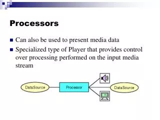
Mixer More signal at higher freq. Proven solution ADC performs better at IF LO generation + distribution New cables in LINAC needed Baseband vs. Mixer Baseband • Simpler • Cheaper • Use existing cables (?) • Only marginally meets resolution requirements
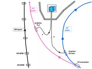
System Overview Calibration scheme does not require extra cables Direct digitization
Status • VME Digitizers + basic driver software available • Echotek • Joerger • SIS • New card ordered (13ENOB, 130MSPS, 700MHz input BW) • First frontend design + prototype (E. Medvedko) • Engineer hired (M. Cecere)
Frontend • f0 =150MHz (enough signal, ADC still well performing) • Low noise, 10MHz BW • Low distortion • Alias suppression • Build Prototype • Test (noise, stability, out-of band performance, linearity) • Final Design • Interface (form factor, control signals, status monitors) • Calibration
LNA ADC BPM Analog Front EndBaseband Design BPF#2 BPF#1 Signal from BPM or Hybrid Frequency Selection Filter Band Pass Filter Undersampling ADC Low Noise Amplifier Final Amplifier
LNA ADC Baseband DesignComponent Selection Criteria BPF#2 BPF#1 Freq./BW determine SNR Low Insertion Loss Good OOB rejection Sharp Rolloff (Anti- alias) Flat Passband >= 119MSPS High Dynamic Range BW>= 200MHz Low NF Low Distortion Moderate Gain High Gain*BW Low Distortion @ High Output Level
LNA ADC Baseband DesignComponents Alias image @ 30MHz BPF#2 BPF#1 Cable NF = 2-4dB NF = 3dB NF = 2-4dB LTC2208 130MSPSmax 16-bit 700MHz BW fsamp=119MHz Req. jitter < 350fs --------------------- AD6645 105MSPSmax 14-bit 200MHz BW fsamp=102? Req. jitter < 600fs fo= 150MHz BW = 10MHz Lark Engineering MS140-20-3CC Insert. Loss = 5.8dB -------------------------- TTE filters KB3T-150M-10M-50-3A Insert. loss = 4.1dB -------------------------- Microwave Filter Co. 3MB10-150/10-SF/SF-1 Insertion loss = 3dB TI OPA847 GBW = 3.9GHz Distortion -105dBc Sirenza SGA-6589 G = 26dB NF = 3.0dB OIP3 = 33dBm ------------------- Sirenza SGA-4363 G = 18dB NF = 3.1dB OIP3 = 29dBm Sawtek 854916 fo= 150MHz BW = 10MHz Insert. loss = 11dB
Baseband DesignFrequency Response dBm Final output BPM signal Input signal Cable losses LNA BPF2 BPF1 Frequency MHz
Mixer Based BPMBlock Diagram xN 43MHz 400-800MHz BPM ADC LNA RF IF or Hybrid LO 119MHz Minicircuits ZFM-2 1 – 1000 MHz Conv Loss = 5.8dB
Mixer Based DesignFrequency Response dBm mixer BPM signal After coax LNA BPF1 BPF2 Frequency MHz
Calibration Bench Test • Measurement setup (not worse than required stability!!) • Test stability of calibration (splitters, BPM striplines) • Cross-talk issues? • Repeatability • Multiplexing (t/f) • Final design, integration
Software Tasks • Evaluation / test software • BPM Processor • Processing algorithm • Real-time tasks: • data acquisition and processing • timing • history buffers • Calibration • Integration (SLC-aware IOC, timing, feedback) • Slow controls (gain, calib, status monitors, alarms)
Integration; Hardware • Clock generation and distribution • Timing; triggers/gates • Calibration signal generation and distribution • Controls: gain, calib. mux • Power • Status monitors
Integration; Software • Timing • SLC-aware layer • Shot-to-shot feedback • High-level applications (EPICS database) • Naming • Real-time • Sysadmin; infrastructure; network