Download
1 / 44
490 likes | 884 Vues
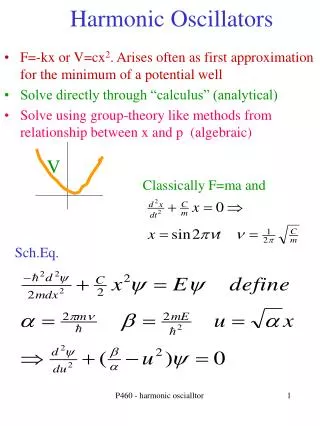
OSCILLATORS. Oscillators. Objectives. Describe the basic concept of an oscillator Discuss the basic principles of operation of an oscillator Analyze the operation of RC, LC and crystal oscillators Describe the operation of the basic relaxation oscillator circuits. Oscillators. Introduction.

E N D
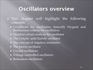
Oscillators Objectives • Describe the basic concept of an oscillator • Discuss the basic principles of operation of an oscillator • Analyze the operation of RC, LC and crystal oscillators • Describe the operation of the basic relaxation oscillator circuits
Oscillators Introduction Oscillators are circuits that produce a continuous signal of some type without the need of an input. These signals serve a variety of purposes. Communications systems, digital systems (including computers), and test equipment make use of oscillators.
Oscillators Oscillator is an electronic circuit that generates a periodic waveform on its output without an external signal source. It is used to convert dc to ac. The waveform can be sine wave, square wave, triangular wave, and sawtooth wave.
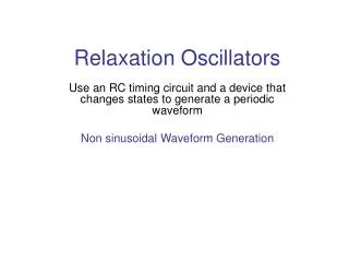
Oscillators An oscillator is a circuit that produces a repetitive signal from a dc voltage. The feedback oscillator relies on a positive feedback of the output to maintain the oscillations. The relaxation oscillator makes use of an RC timing circuit to generate a nonsinusoidal signal such as square wave.
Oscillators Types of oscillators 1. RC oscilators - Wien Bridge - Phase Shift 2. LC oscillators - Hartley - Colpitts 3. Relaxation oscilators
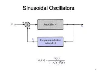
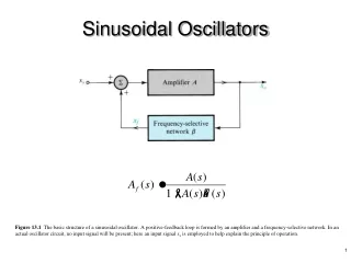
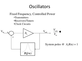
Oscillators Basic principles for oscillation • An oscillator is an amplifier with positive feedback.
Oscillators The closed loop gain is;
Oscillators In general A and are functions of frequency and thus may be written as; is known as loop gain
Oscillators Writing the loop gain becomes; Replacing s with j; and
Oscillators At a specific frequency f0; At this frequency, the closed loop gain; will be infinite, i.e. the circuit will have finite output for zero input signal - oscillation
Oscillators Thus, the condition for sinusoidal oscillation of frequency f0 is; This is known as Barkhausen criterion.
Oscillators The feedback oscillator is widely used for generation of sine wave signals. The positive (in phase) feedback arrangement maintains the oscillations. The feedback gain must be kept to unity to keep the output from distorting. If the feedback circuit returns the signal out of phase, an inverting amplifier produces positive feedback.
Oscillators Design Criteria for Oscillators 1. The magnitude of the loop gain must be unity or slightly larger i.e. – Barkhaussen criterion 2. Total phase shift, of the loop gain must be 0° or 360°.
Oscillators Factors determining the frequency of oscillation • Oscillators can be classified into many types depending on the feedback components, amplifiers and circuit topologies used. • RC components generate a sinusoidal waveform at a few Hz to kHz range. • LC components generate a sine wave at frequencies of 100 kHz to 100 MHz. • Crystals generate a square or sine wave over a wide range,i.e. about 10 kHz to 30 MHz.
Oscillators 1. RC Oscillators
Oscillators 1. RC Oscillators RC feedback oscillators are generally limited to frequencies of 1 MHz or less. The types of RC oscillators that we will discuss are the Wien-bridge and the phase-shift.
The Wien-Bridge Oscillator Oscillators – Wein–bridge oscillator RC feedback is used in various lower frequency sine-wave oscillators. The text covers three: the Wien-bridge oscillator, the phase-shift oscillator, and the twin-T oscillator. The feedback circuit in a Wien-bridge uses a lead-lag circuit. When the R’s and C’s have equal values, the output will be ⅓ of the input at only one frequency and the phase shift at this frequency will be 0o.
Oscillators – Wien-bridge The lead-lag circuit of a Wien-bridge oscillator reduces the input signal by 1/3 and yields a response curve as shown. The frequency of resonance can be determined by the formula below.
Oscillators – Wien-bridge It is a low frequency oscillator which ranges from a few kHz to 1 MHz. Structure of this oscillator is shown below; Voltage-divider Lead-lag network
Oscillators – Wien-bridge The lead-lag circuit of a Wien-bridge oscillator reduces the input signal by 1/3 and yields a response curve as shown. The frequency of resonance can be determined by the formula below.
Oscillators – Wien-bridge The loop gain for the oscillator is where; and;
Oscillators – Wien-bridge Hence; Substituting for s;
Oscillators – Wien-bridge For oscillation frequency f0; Since at the frequency of oscillation, T(j) must be real (for zero phase condition), the imaginary component must be zero i.e.;
Oscillators – Wien-bridge Which gives us;
Oscillators – Wien-bridge From the previous equation; the magnitude condition is; or; To ensure oscillation, the ratio R2/R1 must be slightly greater than 2.
Oscillators – Wien-bridge With the ratio; then; K = 3 ensures the loop gain of unity – oscillation. - K > 3 : growing oscillations - K < 3 : decreasing oscillations
Oscillators – Wien-bridge The lead-lag circuit is in the positive feedback loop of Wien-bridge oscillator. The voltage divider limits the gain. The lead lag circuit is basically a band-pass with a narrow bandwidth.
Oscillators – Wien-bridge Since there is a loss of about 1/3 of the signal in the positive feedback loop, the voltage-divider ratio must be adjusted such that a positive feedback loop gain of 1 is produced. This requires a closed-loop gain of 3. The ratio of R1 and R2 can be set to achieve this.
Oscillators – Wien-bridge To start the oscillations an initial loop gain greater than 1 must be achieved.
Oscillators – Wien-bridge oscillator using back-to-back zener diode The back-to-back zener diode arrangement is one way of achieving this.
Oscillators – Wien-bridge When dc is first applied the zeners appear as opens. This allows the slight amount of positive feedback from turn on noise to pass. The lead-lag circuit narrows the feedback to allow just the desired frequency of these turn transients to pass. The higher gain allows reinforcement until the breakover voltage for the zeners is reached.
Oscillators – Wien-bridge oscillator using a JFET negative feedback loop Automatic gain control is necessary to maintain a gain of exact unity. The zener arrangement for gain control is simple but produces distortion because of the nonlinearity of zener diodes. A JFET in the negative feedback loop can be used to precisely control the gain. After the initial startup and the output signal increases, the JFET is biased such that the negative feedback keeps the gain at precisely 1.
Oscillators – Wien-bridge When the R’s and C’s in the feedback circuit are equal, the frequency of the bridge is given by Example: What is fr for the Wien bridge? 10 kW 4.7 nF Solution: 680 W 680 W 4.7 nF 1.0 kW 10 kW 1.0 mF = 48.9 kHz
Oscillators – Phase-shift The three RC circuits combine to produce a phase shift of 180o. Fig. 3 shows a circuit containing three RC circuits in its feedback network called the phase-shift oscillator.
Oscillators – Phase-shift The phase shift oscillator utilizes three RC circuits to provide 180º phase shift that when coupled with the 180º of the op-amp itself provides the necessary feedback to sustain oscillations. The gain must be at least 29 to maintain the oscillations. The frequency of resonance for the this type is similar to any RC circuit oscillator.
Oscillators – Phase-shift Phase-shift network The transfer function of the RC network is
Oscillators – Phase-shift If the gain around the loop equals 1, the circuit oscillates at this frequency. Thus for the oscillations we want, or;
Oscillators – Phase-shift Putting s = j and equating the real parts and imaginary parts to zero at = o, we obtain; Imaginary part:
Oscillators – Phase-shift Real part: Conditions for oscillation with the phase-shift oscillator is that if all R’s and C’s are equal, the amplifier must have a gain of at least 29 to make up for the attenuation of the feedback circuit. This means that Rf /R3≥ 29.
Oscillators – Phase-shift Even with identical R’s and C’s, the phase shift in each RC circuit is slightly different because of loading effects. When all R’s and C’s are equal, the feedback attenuates the signal by a factor of 29. The last R has been incorporated into the summing resistors at the input of the inverting op-amp.
Oscillators – Phase-shift Design a phase-shift oscillator for a frequency of 800 Hz. The capacitors are to be 10 nF. Start by solving for the resistors needed in the feedback circuit: 8.12 kW (Use 8.2 kW.) Calculate the feedback resistor needed: 238 kW Rf = 29R = 238 kW. 10 nF 10 nF 10 nF 8.2 kW 8.2 kW 8.2 kW