Download
1 / 47
480 likes | 645 Vues
Supported by. HHFW and EBW Heating and Current Drive 5-Year Research Plan. Columbia U Comp-X General Atomics INEL Johns Hopkins U LANL LLNL Lodestar MIT Nova Photonics NYU ORNL PPPL PSI SNL UC Davis UC Irvine UCLA UCSD U Maryland U New Mexico U Rochester U Washington

E N D
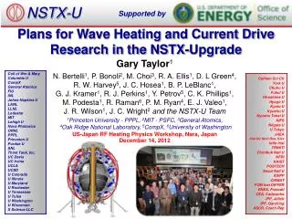
Supported by HHFW and EBW Heating and Current Drive 5-Year Research Plan Columbia U Comp-X General Atomics INEL Johns Hopkins U LANL LLNL Lodestar MIT Nova Photonics NYU ORNL PPPL PSI SNL UC Davis UC Irvine UCLA UCSD U Maryland U New Mexico U Rochester U Washington U Wisconsin Culham Sci Ctr Hiroshima U HIST Kyushu Tokai U Niigata U Tsukuba U U Tokyo Ioffe Inst TRINITI KBSI KAIST ENEA, Frascati CEA, Cadarache IPP, Jülich IPP, Garching U Quebec Gary Taylor Princeton Plasma Physics Laboratory For the NSTX National Team DOE Review of NSTX Five-Year Research Program Proposal June 30 – July 2, 2003
Outline • Motivation • High Harmonic Fast Waves (HHFW) - Research Goals - Status: - HHFW System - Experimental Results - Theory & Modeling - 5-Year Plan • Electron Bernstein Waves (EBW) - Research Goals - Status: - Mode ConversionTheory - Mode Conversion & Coupling Experiments - Technology Issues - 5-Year Plan
HHFW & EBW Provide Tools for Local Electron Heating and Current Drive in High b, ST Plasmas • High b scenarios require off-axis CD to complement bootstrap and NBI CD • On-axis RF CD is also required for solenoid-free current ramp-up and steady-state operation • Lower hybrid and conventional ECCD cannot be used in high b ST plasmas, where wpe >> wce • HHFW in high b plasmas have strong single pass electron absorption, so potential for desired off-axis deposition • EBW propagate in an ST plasma & are strongly absorbed at EC resonances; potentially allowing local EBWH & EBWCD
HHFW 5-Year Research Goals • HHFW-assisted current ramp-up • Pressure profile modification • HHFW CD-assisted discharge sustainment • Use HHFW, with other tools, for tpulse > tskin operation
Flexible High Power HHFW Heating and CD System Operational on NSTX • Uses TFTR ICRF hardware • f = 30 MHz, w/WD = 9-13 • 6 MW from 6 transmitters • Pulse length up to 5 s • 12 Element antenna • Active phase control • kT = ± (3-14) m-1 - variable during shot B • Digital phase feedback sets phase between straps • BN insulators to minimize RF sheaths P. Ryan, et al., Fus. Eng. & Design, 56-57, 1395 (2001)
HHFW Primarily Heats Electrons when Ti < 2 keV, as Expected from Theory • No evidence for direct thermal ion heating • HHFW heats ions when Ti ≥ 2keV and bi significant • Confinement generally consistent with ITER scalings
Some HHFW-Heated Discharges Exhibit Internal Transport Barrier Behavior • Te increases strongly inside half radius • Density profile doesn’t show change • Ti (0) rises with Te(0) • ce progressively decreases with time in the central region 5 Prf = 2.5 MW, Ip = 800 kA LARGE Te INCREASE 4 3 Te (keV) 2 1 0 0.2 1.4 0.6 1.0 R (m)
Less Loop Voltage to Maintain IP With Co Phasing; Magnetics Analysis Estimates Icd = 110 kA (0.05 A/W) 1.0 0.8 Counter-CD DV ≈ .23V 0.6 Loop Voltage (V) Co-CD 0.4 0.2 RF on 0 0.6 0.5 0.4 0.2 0.3 Time (s) 1.0 Counter-CD (1.1 MW) DV = 0.23 V Loop Voltage (V) • Plasmas matched for central Te Co-CD (2.1 MW) kT = ±7 m-1 HHFW On 0 0.6 0.2 Time (s) • TORIC Icd = 95 kA (0.05 A/W) • CURRAY Icd = 162 kA (0.08 A/W)
HHFW CD Efficiency Consistent with DIII-D & TFTR CD; But Significant Off-Axis HHFW CD not Expected • More RF power & improved confinement regime should increase Te to meet original estimate for on-axis HHFW CD Original Estimate for NSTX On-axis CD C. Petty et al., Plasma Physics and Controlled Fusion 43 (2001) 1747 • Present results are for on-axis HHFW CD • Trapping can significantly reduce off-axis CD efficiency: • - High b may reduce trapping
Codes Predict Strong Electron Damping, as Seen in Experiments HPRT • Good agreement between ray tracing codes (CURRAY, HPRT) • Full-wave codes predict similar deposition to ray tracing: - Full-wave kinetic models predict no significant mode conversion • - More modeling needed to • determine if mode conversion • important at higher B and/or ion b 2.1 MW Co-Phasing 2 Pe (MW/m3) 1 CURRAY HPRT 1 1/2
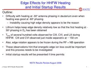
Evidence Seen for HHFW Interactions with Energetic Beam Ions, as Predicted 12 10 8 6 4 2 80 120 100 60 140 40 20 Energy (keV) B0=4.5 kG B0=4.0 kG B0=3.5 kG B0=4.5 kG, bt = 5.2% B0=4.0 kG,bt = 6.6% B0=3.5 kG, bt = 8.6% ln (flux / Energy1/2) beam injection energy NPA HHFW NBI • Tail reduced at lower B, higher b: • - Larger promotes greater off-axis electron absorption • reducing power available to central fast ion population
High b Poloidal H-Mode Plasmas Provide PromisingCandidate for Long Pulse Sustainment Ip (MA) • Vloop ~ 0 • ~ 40% bootstrap fraction
5-Year Plan is Focused on Evaluating the Effectiveness of HHFW as an ST Research Tool • Plan has five major components: - Dependence of coupling on plasma configuration & density - Heating & coupling with NBI and profile modification - HHFW current drive studies - Solenoid-free plasma startup - Technical performance improvements
Dependence of Coupling on Plasma Configuration & Density 2004: • Investigate thermal ion heating; use H-mode plasmas & new • X-ray crystal Ti diagnostic • Vary inner & outer gaps in double null discharge; previously • only studied in limiter and lower single null plasmas • Study effect of varying density on heating efficiency over • a wider range of density
Heating & Coupling with NBI & Profile Modification 2004: • Modify internal inductance with early heating; reduce • volt-sec consumption & increase q(0) • HHFW heating efficiency with strong NBI; study dependence • on target b and density • HHFW H-mode access 2005-6: • Feedback control of HHFW heating at high b to broaden • electron pressure profile
HHFW Current Drive Studies 2004-5: • Measure J(R) with motional stark effect (MSE) diagnostic • Dependence of CD efficiency on RF power, density, • temperature and antenna phasing • 2006: • Study reduction in off-axis CD efficiency due to trapping • and possible increase in CD efficiency at high b 2007-8: • Feedback antenna phasing on MSE J(R) & rtEFIT • HHFW with full feedback control of antenna phase • using MSE LIF system for real time J(R), & P(R)
Solenoid-Free Plasma Startup 2004-5: • Couple into Coaxial Helicity Injection (CHI) startup plasma • HHFW heating with CHI to develop bootstrap current • HHFW CD phasing with CHI for direct current drive • 2006-7: • HHFW handoff to NBI during current ramp up 2007-8: • Minimize flux consumption with HHFW to enable long pulse, • high b, non-inductive plasmas
Technical Performance Improvements 2004-5: • Continue dedicated experiments to elucidate HHFW antenna • power limits & reliability issues; recent modifications increased • voltage limit by ~ 40% • Possibly modify HHFW antenna to double-end fed; • reduces voltage for same power & removes hard ground
EBW May Allow Highly Localized Heating & Current Drive in ST Plasmas • EBW propagate & are strongly absorbed at EC resonances in ST plasma; potentially allowing local EBWH & EBWCD • Electromagnetic waves can couple to EBW via two mode conversion processes: X-B Conversion: X-mode launch perpendicular to B field couples to EBW when Ln is short at the upper hybrid resonance (UHR) O-X-B Conversion: Near-circular polarization launch at oblique angle to B field couples to EBW when angle set to make wp and wL cutoffs coincide
EBW 5-Year Research Goals • Demonstrate efficient coupling to EBW via X-B and O-X-B conversion • Control spatial location where EBWs damp and heat electrons; optimize J(R) for High b operation • Test EBW-assisted non-inductive current startup, alone, or in combination with HHFW and/or CHI • Test suppression of neoclassical tearing modes with EBW current drive • Plan to install ~ 1 MW of RF source power by 2006, increasing to ~ 4 MW by 2008
EBW Emission Experiments on CDX-U and NSTX Focused on Maximizing B-X Conversion in Scrape Off Layer 100 • EBW to X-mode conversion efficiency (CBX) very sensitive to Ln: EBW Emission Frequency = 6 GHz CBX (%) • B-X emission evaluates efficiency of X-B process for heating and CD CBX = 98% @ Ln = 0.5 cm 0 0 1.0 2.0 3.0 Ln (cm) A.K. Ram & S.D. Shultz, Phys. Plasmas, 7, 4084 (2000) A.K. Ram, et al., Phys. Plasmas, 9, 409 (2002)
Local O-X-B Heating Demonstrated on W-7AS Stellarator EBWH 15 Diamagnetic Energy (kJ) 0 NBI (MW) 2 EBWH (MW) 0 400 600 200 Time (ms) • Te increased from 270 to 310 eV with 1.5 MW EBWH over ~ 3 cm radius W7-AS H.P. Laqua, et al., Phys. Rev. Lett. 78, 18 (1997)
On CDX-U, Limiter Shortened Ln to 0.7cm, Increasing CBX to > 95%, in Good Agreement with Theory B. Jones et al., Phys. Rev. Lett. 90, 165001 (2003)
Need CBX> 80% for Viable EBW Heating & CD System • CBX < 5% for L-Mode and 10-15% for H-Mode on NSTX in 2001 • Experiment on NSTX using HHFW antenna tiles to shorten Ln last year achieved CBX≤ 50% • Next year, demonstrate CBX> 80% on NSTX using installed antenna with optimized local limiter • Also, installed B-X-O antenna on NSTX for EBW emission measurements next year • Collaboration begun with MAST O-X-B heating experiments
EBW Heating and CD May Optimize Equilibrium for High b Plasmas by Suppressing Deleterious MHD • Fully non-inductive, b ~ 40% plasma requires ~ 150 kA externally driven current between r/a = 0.4 and 0.8 • NTM's may grow at q = 1.5 and q = 2 surfaces located between r/a = 0.3 and 0.5, in high b plasma • EBW heating and CD being modeled with GENRAY ray tracing & CQL3D Fokker-Planck codes • Recent modeling results indicate EBWCD in NSTX is dominated by Okhawa CD at r/a > 0.3; increases with r/a
Placing EBW Launcher Well Above or Below MidplaneProduces Large n// Shifts Needed for Efficient EBWCD GENRAY GENRAY 15 GHz RF launched at 65o above mid-plane, with 0.5 < n// < 0.7 into b = 30% NSTX equilibrium
Radial Location of EBWCD is Highly Localized and can be Varied by Changing Launched n// 1.0 40 • Positive current results from Okhawa CD • Plan ~ 4 MW at RF source power to get > 100 kA ; efficiency increases with r/a • Normalized CD efficiency, ec= 0.4, compares favorably to ECCD EBWCD Efficiency (kA/MW) Peak Current Density (A/cm2) 30 0.8 0.6 20 r/a Location of Peak EBWCD Density 10 0.4 0.2 0 R. Harvey, CompX CQL3D 0 -10 -2 -1 1 2 0 Launched n// 1 MW of 15 GHz RF launched at 65o above mid-plane, into b = 30% NSTX equilibrium
Status of EBW RF Technology • NSTX plasmas require fundamental EBW RF source frequencies ~ 15 GHz • No long pulse, high power sources in this frequency range • MIT proposes 1 MW tube design with ~ 50% efficiency; requires 18-24 month development: - Will issue cost & schedule quote this year • MIT tube design has TE02 output, TE02 to HE11 converter design already available from GA • Use low-loss corrugated HE11 transmission line, also available from GA
Design Requirements for EBW RF Launcher • More modeling needed to define design requirements for launcher • Need well defined n// spectrum, good focusing and some beam steering • Use steerable focusing mirror launcher • Polarization control by grooved mirror • May use local limiter and/or localized gas puffing to steepen Ln at mode conversion layer: - to improve X-B tunneling - widen O-X-B angular launch window
EBW Research in 2003 • Complete GENRAY/CQL3D scoping study for NSTX; including modeling of EBW-assisted plasma startup • Theoretically determine importance of relativistic effects in EBW propagation & damping; may need to include in scoping study • Estimate threshold for driving edge parametric instabilities • Complete conceptual design for EBW launcher • Request quote for ~ 1 MW gyrotron • MAST begins testing O-X-B heating
EBW Research in 2004-5 • Obtain ≥ 80% B-X and/or B-X-O conversion on NSTX • Complete design of the EBW heating and current drive system • Include radial transport effects in CQL3D modeling of EBW current drive
EBW Research in 2006 • Complete installation of 1 MW EBW system • Demonstrate EBW heating with ~ 1 MW RF source • Look for evidence of RF-driven parametric instabilities • Study spatial control of electron heating • Look for suppression of NTMs
EBW Research in 2007-8 • Begin experiments with 4 MW EBW system • Demonstrate plasma current generation & control • Study plasma EBW startup • Investigate NTM suppression by EBWCD
HHFW and EBW Heating and Current Drive Provide Critical Tools Supporting NSTX Research HHFW: • Heating and current drive for plasma startup and sustainment studies • Powerful heating for high band high bplasma sustainment studies EBW: • Heating and current drive for startup and sustainment studies • Neoclassical Tearing Mode control • Heating and current profile control for high b sustainment studies
FY02 03 04 05 06 07 08 09 IPPA: 10 yr IPPA: 5 year HHFW heating : density, configuration dependence 6 MW HHFW, with NBI HHFW and P(r) modification HHFW CD Vloop HHFW CD measure ∆J HHFW: feedback with heating, CD HHFW CD, long pulse, ∆J feedback HHFW wave/particle interactions EBW emission & coupling EBW CD, NTM Control, Startup Optimize Startup CHI & HHFW CHI, HHFW, NBI Ramp to high bp HHFW/EBW Physics MSE CIF MSE LIF (J, Er, P);polarimetry CHERS 18 ch CHERS 51 ch Feedback control of plasma parameters MPTS 20 ch, 60 Hz MPTS Upgrades Edge Reflectometry Fluctuations & wave deposition 7 MW NBI, 3 MW HHFW 7 MW NBI, 6 MW HHFW Upgrade HHFW Feed HHFW Phase Control 1 MW EBW 4 MW EBW HHFW/EBW Tools
HEATING WITH HHFW FOLLOWS PREDICTIONS OF CONVENTIONAL SCALING Ip= 500 kA BT= 4.5 kG <ne> =1.5 x10¹⁹ m-3 H mode defined by appearance of edge pedestal P.M. Ryan D.W. Swain
Time trace for ne and Te at high and low B • Lower B, higher t shot has same current, similar Te as low t • ne after NBI turn-on somewhat larger at lower B • Neutron rate before RF turn-on larger at lower B
ne,Te, te profiles at high and low B, t = 235 ms • ne profile difference evident • Midplane te profile difference far more prominent
nd, nf, profiles at high and low B, t = 235 ms • Using measured Zeff and TRANSP, nfast and nd determined • Neutron rate nd nf, consistent with trace before RF • RF-induced enhancement would be stronger if densities equal
Peak Diffusion in Vicinity of Trapped-Passing BoundaryEnables Strong Ohkawa Current Drive 15 GHz RF launched at 65o above mid-plane, with 0.5 < n// < 0.7 into b = 30% NSTX equilibrium