Download
1 / 59
590 likes | 930 Vues
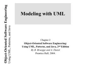
Modelling with UML . CS223 Lecture 4 ( see BD Ch. 2 ) Ananda Amatya Notice : Surgery Sessions (Weeks 6-10) Mon 2 - 4 in C1.01 & Fri 9 - 11 in C1.04 Please attend any one session convenient to you. Overview: modelling with UML. What is modelling ? What is UML ? Use case diagrams

E N D
Modelling with UML CS223 Lecture 4 (see BD Ch. 2) Ananda Amatya Notice: Surgery Sessions (Weeks 6-10) Mon 2 - 4 in C1.01 & Fri 9 - 11 in C1.04 Please attendany onesession convenient to you
Overview: modelling with UML • What is modelling? • What is UML? • Use case diagrams • Class diagrams • Sequence diagrams (Collaboration diagrams) • Activity diagrams • StateChartdiagrams
What is modelling? • Modelling • building an abstraction of reality. • Abstractions • simplifications: • ignore irrelevant details • focus on matters of concern. • What is relevant and what is irrelevant? • depends on the purpose of the model.
Why model software? • More sophisticated software means more complexity: • Windows XP > 40 million lines of code; • Several coders must be involved. • One developer’s code must be understood by another developer. • Complex systems must be simplified: • Modelling is a way of achieving this.
Systems, Models and Views • System: an organised set of communicating parts. • Model: an abstraction describing a subset of a system. • View: a selected aspect of a model. • Notation: a set of graphical or textual rules for depicting views. • Views and models of a single system may overlap each other. • Examples: • System: Aircraft • Models: Flight simulator, scale model • Views: All blueprints, electrical wiring, fuel system
Systems, Models and Views Blueprints Flightsimulator Aircraft Fuel System Scale Model Electrical Wiring
Models, Views and Systems (UML) * * System Model View Depicted by Described by Airplane: System Scale Model: Model Flight Simulator: Model Blueprints: View Fuel System: View Electrical Wiring: View
Concepts and Phenomena • Phenomenon: • An object in the world of a domain as you perceive it. • Examples:this lecture, that wall clock • Concept: • An abstraction that describes phenomena with common properties. • Examples:Lecture, Wall clock • Concept is a 3-tuple: • Name (to distinguish one concept from another) • Purpose (to determine if a phenomenon belongs to a concept) • Members (the set of phenomena that belong to theconcept - instances)
Name Purpose Members Clock A device that measures time. Concepts and Phenomena (contd.) • Abstraction • Classification of phenomena into concepts • Modelling • Development of abstractions to answer specific questions about a set of phenomena while ignoring irrelevant details.
Concepts in software: Type and Instance • Type: • An abstraction in the context of programming languages • Name: int, • Purpose: integral number, • Members: 0, -1, 1, 2, -2, . . . • Instance: • Member of a specific type • The type of a variable represents all of its possible instances • The following relationships (<–>) are similar: • “type” <–> “instance” • “concept” <–> “phenomenon”
Abstract Data Types & Classes • Abstract data type: • Special type whose implementation is hidden from the rest of the system. • Class: • An abstraction in the context of object-orientedlanguages • Like an abstract data type, a class encapsulates bothstate (variables) and behaviour (methods) • Example Class: Watch • Unlike abstract data types, classes can bedefinedin terms of other classes using inheritance
Application and Solution Domain • Application Domain (Requirements Analysis): • The environment in which the system is operating • Solution Domain (System Design, Object Design): • The available technologies to build the system
Object-oriented modelling Application Domain Solution Domain UML Package TrafficControl SummaryDisplay MapDisplay TrafficController FlightPlanDatabase Aircraft Airport TrafficControl FlightPlan System Model Application Domain Model
What is UML? • UML (Unified modelling Language) • A standard for modelling object-oriented software. • Resulted from the convergence of notations from: • OMT (James Rumbaugh) • OOSE (Ivar Jacobson) • Booch (Grady Booch) • Reference: OMG (Object Management Group) • Supported by several CASE tools • Rational ROSE (IBM) • Poseidon (ArgoUML) • TogetherJ (Borland) • Rhapsody (ILogix) • Eclipse (IBM) • …
UML: First Pass • You can model 80% of most problems by using about 20% UML • We teach you those 20%
UML First Pass • Use case Diagrams • describe a system’s functional behaviour as seen by its user. • Class diagrams • describe a system’s static structure: Classes, Associations • Sequence diagrams • describe a system’sdynamic behaviour: actors, objects, messages • Statechart diagrams • describe the dynamic behaviourof individual objects of the system: states, events, transitions • Activity Diagrams • model a system’sdynamic behaviour: activities, workflows (flowcharts)
Watch ReadTime SetTime WatchUser WatchRepairPerson ChangeBattery UML first pass: Use case diagrams Use case Package Actor Use case diagramsrepresent thesystem’sfunctionality fromuser’s point of view
1 1 1 2 1 1 LCDDisplay Battery load Time now blinkIdx blinkSeconds() blinkMinutes() blinkHours() stopBlinking() referesh() UML first pass: Class diagrams Association Class Multiplicity Watch 1 2 PushButton state push()release() Attribute Operations Class diagrams represent the structure of the system
:Watch :LCDDisplay :Time :WatchUser pressButton1() blinkHours() pressButton1() blinkMinutes() pressButton2() incrementMinutes() refresh() pressButtons1And2() commitNewTime() stopBlinking() UML first pass: Sequence diagram Actor Object Message Activation Lifeline Sequence diagrams represent the behaviouras interactions
UML first pass: Statechart (diagrams) for objects with interesting dynamic behaviour State Event Initial state [button2Pressed] [button1&2Pressed] IncrementHrs BlinkHours Transition [button1Pressed] [button2Pressed] [button1&2Pressed] IncrementMin. BlinkMinutes [button1Pressed] [button2Pressed] [button1&2Pressed] BlinkSeconds IncrementSec. Final state StopBlinking Statecharts represent behaviourasstatesand transitions
Other UML Notations • UML provide other notations • Implementation diagrams • Component diagrams (BD Chapter 7) • Deployment diagrams (BD Chapter 7) • UMLincludes OCL (Object constraint language) • Used in Design (BD Chapter 9) • And then … there is UML 2 (a major revision of UML) • For a good introduction see • IBM Webcast Recorded EventFeb15 Intro.itm in http://developer.raindance.com/iccdoc
UML Core Conventions • Rectangles are classes or instances • Ovalsare functions or use cases • Instances are denoted with underlined names • Examples: myWatch:SimpleWatch, Joe:Firefighter • Types are denoted with non-underlined names • Examples:SimpleWatch, Firefighter • Diagrams are graphs • Nodes are entities • Arcs are relationships between entities
Used during requirementselicitation to capture a system’s external behaviour An Actor represents a user’s role, that is, the type of a user of the system A Use case represents a sequence of interactions for a type offunctionality A use case model is the set of all the use cases for a system and its environment, i.e., a complete description of all the functionalities of the system and its environment Passenger PurchaseTicket Use Case Diagrams
An actor models an external entity which communicates with the system: User External system Physical environment An actor has a unique name and an optional description. Examples: Passenger: A person using a train GPS satellite: AProvider of GPS coordinates to the system Passenger Actors
A use case represents a class of functionality provided by the system as an event flow. A use case consists of: Unique name Participating actors Entry conditions Flow of events Exit conditions Special requirements PurchaseTicket Use Case
Name:Purchase ticket Participating actor:Passenger Entry condition: Passenger standing in front of ticket distributor. Passenger has sufficient money to purchase ticket. Exit condition: Passenger has ticket. Event flow: 1. Passenger selects the number of zones to be travelled. 2. Distributordisplays the amount due. 3. Passenger inserts money, of at least the amount due. 4. Distributor returns change. 5. Distributor issues ticket. Use Case Diagram: Example Anythingmissing? Exceptional cases!
<<extend>> relationships represent exceptional or seldom invoked cases. The exceptional event flows are separated from the main event flow for clarity. A use case representing exceptional event flows may extend one or more use cases. The direction of a <<extend>> relationship is to the extended use case Passenger PurchaseTicket <<extend>> OutOfOrder TimeOut <<extend>> <<extend>> <<extend>> Cancel NoChange The <<extends>> Relationship
<<include>> relationship represents behaviour that is factored out of the use case. <<include>> behaviour is factored out for reuse, not because it is an exception. The direction of a <<include>> relationship is to the using use case (unlike <<extend>> relationships). Passenger PurchaseMultiCard PurchaseSingleTicket <<include>> <<include>> NoChange Cancel CollectMoney <<extend>> <<extend>> The <<includes>> Relationship
Use Case Diagrams: Summary • Use case diagrams represent external behavior • Use case diagrams are useful as an index into the use cases • Use case descriptions (flow of events) provide meat of model, not the use case diagrams. • Alluse cases need to be described (flow of events) for the model to be useful.
zone:Zone Price: Price TarifSchedule Trip Class Diagrams • Class diagrams represent the structure of the system. • Used • during requirements analysis to model problem domain concepts • during system design to model subsystems and interfaces • during object design to model classes. Enumeration getZones() Price getPrice(Zone) * *
TarifSchedule TarifSchedule TarifSchedule Table zone2price Enumeration getZones() Price getPrice(Zone) zone2price getZones() getPrice() Classes Name Signature Attributes Operations • A classrepresent a concept • A class encapsulates state (attributes) and behaviour(operations). • Each attributehas a type. • Each operation has a signature. • The class name is the only mandatory information.
tarif_2004:TarifSchedule Instances zone2price = { {‘1’, .20},{‘2’, .40}, {‘3’, .60}} • An instance represents a phenomenon. • Instance nameis underlined and can show its class. • The attributes are shown with their values. • No operation is shown as it is the same as for its class.
Actor vs Instances • Difference between actor, classand instance: • Actor: • external to the system • interacts with the system • E.g.,“Passenger” • Class: • models an entity in the problem domain • modelled inside the system • E.g.,“TariffSchedule” • Instance: • A specificinstance of a class • E.g., “tarif_2004, the specific TariffSchedule being used by the passenger for purchasing a ticket from the ticket distributor”
TarifSchedule TripLeg Associations Enumeration getZones() Price getPrice(Zone) PriceZone * * • Associations denote relationships between classes. • The multiplicity at an association end denotes how many objects the source object can legitimately reference.
1-to-1 and 1-to-many Associations Has-capital CapitalCity Country name:String name:String One-to-one association Point Has-vertex * Polygon x: Integer y: Integer draw() One-to-many association
Many-to-Many Associations Company Lists * * StockExchange tickerSymbol * 1 Lists Company StockExchange tickerSymbol
From Problem Statement To Object Model ProblemStatement: A stock exchange lists many companies. Each company is uniquely identified by a ticker symbol Class Diagram: Company * * StockExchange Lists tickerSymbol
From Problem Statement to Code Problem Statement: A stock exchange lists many companies. Each company is identified by a ticker symbol Class Diagram: * * Company StockExchange Lists tickerSymbol Java Code: public class StockExchange { private Vector m_Company = new Vector(); }; public class Company { public int m_tickerSymbol; private Vector m_StockExchange = new Vector(); };
Exhaust system TicketMachine ZoneButton 0..2 1 Muffler Tailpipe diameter diameter Aggregation Exhaust system 0..2 1 Muffler Tailpipe diameter diameter • An aggregationis a special case of association denoting a “consists of” hierarchy. • The aggregate is the parent class, the components are the children class. • A solid diamond denotes composition, a strong form of aggregation where components cannot exist without the aggregate. 3
Without qualification File 1 * Directory filename With qualification 1 0…1 Directory filename File Qualifiers • Qualifiers can be used to reducethe multiplicity of an association. • Directory uses filename to makethe association 1:1
CancelButton ZoneButton Button Inheritance • The children classesinherit the attributes and operations of the parent class. • Inheritance simplifies the model by eliminating redundancy.
Object modelling in Practice: Class Identification Foo Quantity CustomerId Deposit() Withdraw() GetBalance() Class Identification:Name of Class, Attributes and Methods
Object modelling in Practice: Encourage Brainstorming Foo Quantity CustomerId Deposit() Withdraw() GetBalance() Account Quantity CustomerId Deposit() Naming is important! Is Foo the right name? Withdraw() GetBalance()
Account Quantity Customer Bank Name Name AccountId Deposit() Withdraw() GetBalance() Object modelling in Practice contd. CustomerId CustomerId 1) Find New Objects 2) Iterate on Names, Attributes and Methods
Account Quantity Bank Customer Name Name Deposit() CustomerId Withdraw() GetBalance() Object modelling in Practice: A Banking System * Has CustomerId AccountId 1) Find New Objects 2) Iterate on Names, Attributes and Methods 3) Find Associations between Objects 4) Label the associations 5) Determine the multiplicity of the associations
Account Amount Customer Bank CustomerId Name Name Deposit() Withdraw() GetBalance() Savings Account Checking Account Mortgage Account Withdraw() Withdraw() Withdraw() Practice Object modelling: Iterate, Categorize! * * Has AccountId CustomerId()
Packages • A package is a UML mechanism for organizing elements into groups (usually not an application domain concept) • Packages are the basic grouping constructs with which you may organise UML models to increase their readability. • A complex system can be decomposed into subsystems, where each subsystem is modelled as a package DispatcherInterface Notification IncidentManagement
Class Diagrams: Summary • Class diagrams:system structure • Class: name, attributes (types), operations (signatures) • Instances: underlined names, attribute values • Associations between classes, multiplicities • Qualified Associations: from many:many to 1:1 • Aggregation, composition • Inheritance • Iterate udring class identification, naming, attributes and methods, associations • Packages
Used during requirements analysis To refine use case descriptions to find additional objects (“participating objects”) Used during system design to refine subsystem interfaces Classes are represented by columns Messages are represented by arrows Activationsare represented by narrow rectangles Lifelines are represented by dashed lines TicketMachine Passenger selectZone() insertCoins() pickupChange() pickUpTicket() UML sequence diagrams