Download
1 / 35
350 likes | 355 Vues
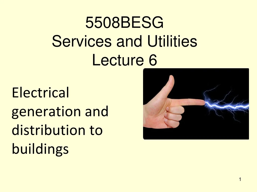
5508BESG Services and Utilities Lecture 6. Electrical generation and distribution to buildings. Electrical Services In Buildings. Essential electrical theory Generation Distribution Systems for buildings Electrical Design. Useful Publications.

E N D
5508BESGServices and Utilities Lecture 6 Electrical generation and distribution to buildings
Electrical Services In Buildings Essential electrical theory Generation Distribution Systems for buildings Electrical Design
Useful Publications CIBSE Electricity in Buildings (Guide K), ISBN 1 903287 26 X BSRIA Illustrated Guide toElectricalBuilding Services, BG5/2005. On site guide to BS7671, the 17th Edition of the Wiring Regulations
Electrical Theory Each basic element has a certain number of electrons and protons, which distinguishes each element from all other basic elements. In mostelements, the number of electrons is equal to the number of protons. This maintains an electrical balance in the structure of atoms since protons and electrons have equal, but opposite electrostatic fields.
A copper atom has 29 protons in its nucleus with 29 electrons orbiting the nucleus. Notice that in the copper atom, the electrons are arranged in several layers called shells The greater distance between the electrons in the outer shells and the protons in the nucleus mean the outer shell electrons experience less of a force of attraction to the nucleus than do the electron in the inner shells. The electron in the outer shell is known as the “valence electron” and because it is only loosely held by the atom these can relatively easily be forced out of orbit of one atom and into orbit around an adjacent atom. In fact this happens all the time within an electrical conductor with the valence electrons drifting at random from one atom to the next.
Electrical Current If some force can act on the atoms such that this random drift is converted into a steady flow of valence electrons from atom to atom an electric current is said to be flowing, thereforean electric current is a flow of electrons in a given direction within a conductor The rate at which the electrons are flowing is measured in units called amperes. The term amps is often used for short. An amp is the amount of electrical current that exists when a number of electrons, move past a given point in one second. 1 Amp = 6,250,000,000,000,000,000. electrons moving past a given point in one second
Voltage To get the electrons to move in a certain direction a force must be applied to cause the movement, this force is known as the electro motive force (emf) but is more usually referred to as Voltage. Electrical engineers sometimes say electrical pressure when they are talking about voltage. It is the force that makes electrons move in a certain direction within a conductor in the same way as pressure difference causes water to move within a pipe.
W • 3 things are necessary in order for electric current to flow. • They are ? • a closed circuit • made of conducting materials (a conductor) • with a voltage difference applied In (a) we have a continuous circuit made from a conductor with billions of valence electrons but without a voltage there is no current. In the same way that in (b) we have a pipe circuit full of water but without the pressure difference created by a pump there is no flow of water (a) (b)
Radiator Water flow Pump provides moving force Appliance Electrical current, amps Electro motive force provided by mains voltage
Resistance There is another important property that can be measured in electrical systems. This is resistance, which is measured in units called ohms. Resistance is a term that describes the forces that oppose the flow of electron current in a conductor. In overcoming the resistance some, or all of the electrical pressure (voltage) is used up. In doing so, the electrical energy is converted into some other form of energy, usually heat, light or magnetic energy, hopefully useful energy.
Resistance & Work All materials naturally contain some resistance to the flow of electric current. Conductors (cables) are made from materials that have as low a resistance as possible (copper, aluminium, silver or gold). We don’t want these to oppose the flow, use up voltage or convert electrical energy into heat etc. Insulators, are made from material with such high resistance that virtually no electrons flow no matter how much voltage is applied (air, glass, PVC, rubber etc) Those materials that have some resistance or that can be configured to have some resistance, are used to make the components that do the work within the circuit e.g. heaters, motors, lights etc.
Appliance Electrical current, amps Electro motive force provided by mains voltage Conductors: very low resistance Virtually all of the resistance within the circuit is provided by the appliance. In this way the appliance is the only part of the circuit where electrical energy is converted into useful output, or work. If the conductors had resistance they would get warm, cable getting hot is not a good idea!!
Electrical theory Voltage (V, measured in volts) is the “pushing” force of an electrical source – electro motive force Current (I, measured in amps, A) is the amount of electricity flowing Resistance (R, measured in ohms, Ω) inhibits the flow of current Power (P, measured in watts, W) is the electrical energy used with respect to time.
mathematical relationships P V V I I R Ohm’s Law V = I R I = V / R R = V / I P = V I i.e. power used is the product of voltage and current
ELECTRICITY GENERATION Essentially the generation process consists of moving a conductor or several conductors through a magnetic field (or vice versa). This converts mechanical energy to electrical energy. With the configuration shown here the electrical supply generated is alternating current.
alternating current • Electrical current is the flow of electrons through a conductor • Direct current (DC) is continuous flow in one direction • Alternating current (AC) electricity alternates back and forth • AC used for distribution • Safer than DC • Voltage can easily be stepped up or down by transformers – useful property as high voltages are needed for long distance transmission • In UK and the EU this motion occurs 50 times per second (i.e. 50 Hz) • AC is created by an AC electric generator, whos speed of rotation determines the frequency.
ELECTRICITY SUPPLY • Electrical power is generated in power stations throughout the country and this energy is synchronised and supplied to a national grid system (grid also connected to continental European) • The nature of the generation process means that alternating AC is generated. • Various fuels used for generation: • Traditional: Coal, Gas, Nuclear Power • Environmentally friendly: Solar, Wind, HEP
Three Phase Generation In the UK & most EU countries, the generator in the power station contain three separate coils not just one. The coils of wire are set at 120 degrees apart so that the induced voltages are out of phase by this angle during each revolution of the rotor, and so a 3 phase supply is generated
Typical power station generator 3 Coils ROTOR ELECTROMAGNET Three sets of wire coils are cut by the rotating magnetic field produced by the electromagnet within the rotor.
Phase Colours Prior to 2004 the three phases were coloured Red, Yellow and Blue, the neutral was black. Since 2004 the standard throughout the EU (including UK) is Brown, Black & Grey, with the neutral being Blue
Distribution Distributed by un-insulated aluminium high voltage cables suspended between pylons A UK national grid exists and connection is also made through to France Distribution is at high voltages but low current to minimise power losses At point of use transformers in sub stations step down voltage to 400V 3-phase Cables located under streets from which supplies to buildings can be connected 400V 3-phase for large buildings 230V 1-phase for dwellings and small buildings
national distribution Power station Sub-station 400/275 kV 25 kV Trans-former Trans-former 11 kV to light industry, hospitals etc. 33 kV to heavy industry Sub-station 11 kV 132 kV Village sub-station Sub-station 25 kV to railway transformer Sub-station 400 V to farms & small commercial users 3 phase, 4 wire 400/230 V underground main see next slide
local distribution • Power stations produce the electricity • Transformers and substations reduce the supply voltage down for the final supply – industrial 400V or residential 230V • Local Distribution is by 3 Phase, 4 wires • The Fourth wire is Neutral @ zero voltage 400/230 v 4 wire supply 230v 400/230 v 4 wire supply 400/230v 400v 230v 400V 230V 400V
Electrical Supplies to Buildings:Domestic Property Single Phase Supply Underground entry – 450mm min below surface Meter Box on new build and refurbishment must be situated on the external wall
DOMESTIC SUPPLY • Meter Box – responsibility of the Supplier • Consumer unit – responsibility of property owner • Circuit distribution board • Circuit Breakers • Safety Features • Main OFF point
Sub-circuits Combined in Consumer unit Distributionboard Responsibility and property of owner Main isolator switch Meter Installed by and property of electricity board Services fuse and neutral link Incoming service cable SCHEMATIC DIAGRAM OF DOMESTIC INCOMING ELECTRICAL SERVICE
Example of electricity meter Records power consumed in kWhrs Fitted in accessible location inside property – or outside on certain types of housing (particularly social housing)
STANDARD SIX-WAY CONSUMER UNIT
Electrical Supplies to Buildings:Non-Domestic Property Final Sub Circuits Single and/or Three Phase Sub-Distribution Board (inc isolator switch) Sub-Distribution Board (inc isolator switch) Sub-Distribution Board (inc isolator switch) Three Phase and Neutral Feeder Cable Three Phase and Neutral Feeder Cable Three Phase and Neutral Feeder Cable Main Distribution Board (inc Main Switch) Additional or alternative power supplies Meter Cut Out Service Fuses and Neutral Link Three Phase and neutral Incoming supply (TP&N)
Other Types of Power Supplies (to supplement mains power supplies.) • Standby generators: an engine driven generator to automatically cut in in the event of mains failure. There will normally be a short interruption between power failure and the generator starting. • Uninterruptible Power Supplies (UPS): Device to maintain power continuously irrespective of mains fluctuations or failures, to maintain supply to sensitive equipment. • Low Carbon CHP, Wind Turbines, Photovoltaic panels, Anaerobic digesters etc: (To be dealt with as a separate lecture.)