Download
1 / 30
300 likes | 313 Vues
Session 2 Classification of cutting tools Geometry of single point cutting tools Systems of description of tool geometry conversion of tool angles from one system to another. Classification of cutting tools. Classification of cutting tools.

E N D
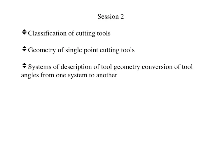
Session 2 • Classification of cutting tools • Geometry of single point cutting tools • Systems of description of tool geometry conversion of tool angles from one system to another
Classification of cutting tools Cutting tools may be classified according to the number of major cutting edges (points) involved as follows: • Single point: e.g., turning tools, shaping, planning and slotting tools and boring tools
Classification of cutting tools • Double (two) point: e.g., drills
Classification of cutting tools • Multipoint (more than two): e.g., milling cutters, broaching tools, hobs, gear shaping cutters etc.
Types of Tools Multipoint Single Point
Cutting edges at the lathe tool 1 tool point, 2 shank, 3 main cutting edge 4 secondary cutting edge
Cutting edges at the lathe tool 1 tool point, 2 shank, 3 main cutting edge 4 secondary cutting edge
The single point cutting tool has only one cutting point or edge. • These tools used for turning, boring, shaping or planning operations. • These tools used on lathe, boring and shaper machines. • A single point cutting tool consists of sharpened cutting part / operating end called as point and shank/ body. • Point of tool is bounded by Face, side/major flank, end/minor flank & base. • Side/ major cutting edge is formed by intersection of face & side flank.
End/ minor cutting edge is formed by intersection of face & end flank. • Chips are cut from w/p by side cutting edges. • Point where end, side cutting edges meet is called nose
Shank: It is main body of tool. • Flank: surface/ surfaces below & adjacent to cutting edge is flank of tool. • Face: Surface on which chip slides is called face of tool. • Nose: It is formed at junction of side & end cutting edges. This junction/ nose has a curve of small radius, know as nose radius.
Cutting Edge: It is the edge on the face of the tool which removes the material from the work piece. The cutting edge consists of the side cutting edge(major cutting edge) and cutting edge(minor cutting edge) and the nose.
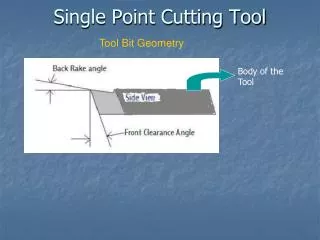
1.Side Cutting Edge Angle: The angle between side cutting edge and the side of the tool shank is called side cutting edge angle. 2.End Cutting Edge Angle: The angle between the end cutting edge and a line perpendicular to the shank of the tool shank is called end cutting edge angle. 3. Side Relief Angle: The angle between the portion of the side flank immediately below the side cutting edge and a line perpendicular to the base of the tool.
4.End Relief Angle: The angle between the end flank and the line perpendicular to the base of the tool is called end relief angle. 5.Back Rake Angle: The angle between the face of the tool and line perpendicular to the base of the tool measures on perpendicular plane through the side cutting edge. 6.Side Rake Angle: The angle between the face of the tool and a line parallel to the base of the tool measured on plane perpendicular to the base and the side edge.
Purposes of conversion of tool angles from one system to another • To understand the actual tool geometry in any system of choice or convenience from the geometry of a tool expressed in any other systems • To derive the benefits of the various systems of tool designation as and when required • Communication of the same tool geometry between people following different tool designation systems.
Methods of conversion of tool angles from one system to another • Analytical (geometrical) method: simple but tedious • • Graphical method – Master line principle: simple, quick and popular • • Transformation matrix method: suitable for complex tool geometry • • Vector method: very easy and quick but needs concept of vectors
Graphical method This convenient and popular method of conversion of tool angles from ASA to ORS and vice-versa is based on use of Master lines (ML) for the rake surface and the clearance surfaces.
Graphical method This convenient and popular method of conversion of tool angles from ASA to ORS and vice-versa is based on use of Master lines (ML) for the rake surface and the clearance surfaces.
Quiz Test Select the correct answer from the given four options : 1. Back rake of a turning tool is measured on its (a) machine longitudinal plane (b) machine transverse plane (c) orthogonal plane (d) normal plane 2. A cutting tool can never have its (a) rake angle – positive (b) rake angle – negative (c) clearance angle – positive (d) clearance angle – negative 3. Inclination angle of a turning tool is measured on its (a) reference plane (b) cutting plane (c) orthogonal plane (d) normal plane
Questions • How is cutting tools classified? • 2. Describe the geometry of single point cutting tools? • 3. Explain the procedure of conversion of tool angles by graphical method?