Download

1 / 58
2.25k likes | 11.44k Vues
An ion beam is a type of particle beam consisting of ions. Ion beams have many uses in electronics manufacturing (principally ion implantation) and other industries. . Definition Of IBM . Principle Of IBM . Ion bombardment at normal incidence to surface. Three types of collision between ion and atom.

E N D
1. Ion Beam Machining
2. Ion beam machining takes place in a vacuum chamber, with charged atoms (ions) fired from an ion source towards a target (the workpiece) by means of an accelerating voltage.
The process works on principles similar to electron beam machining, the mechanism of material removal is quite different.
Ion beam machining (IBM) is closely associated with the phenomenon of sputtering.
Ion beam machining takes place in a vacuum chamber, with charged atoms (ions) fired from an ion source towards a target (the workpiece) by means of an accelerating voltage.
The process works on principles similar to electron beam machining, the mechanism of material removal is quite different.
Ion beam machining (IBM) is closely associated with the phenomenon of sputtering.
3. When an ion strikes the surface of a material it usually collides with an atom there.
This collision often occurs in a direction that is normal to the surface.
On the one hand, if the mass of the ion is less than that of the atom of the surface, the former, will bounce back, away from the surface; and the atom will be driven in a direction further into the material.
On the other hand, if the mass of the incident?? ion is greater than that of the surface atom,
after collision, the ion and atom move from the position of collision towards the interior of?? the surface of material.
Usually both particles move into the material at energies that are less than that of the incident ion, yet much greater than the lattice energy.
When an ion strikes the surface of a material it usually collides with an atom there.
This collision often occurs in a direction that is normal to the surface.
On the one hand, if the mass of the ion is less than that of the atom of the surface, the former, will bounce back, away from the surface; and the atom will be driven in a direction further into the material.
On the other hand, if the mass of the incident?? ion is greater than that of the surface atom,
after collision, the ion and atom move from the position of collision towards the interior of?? the surface of material.
Usually both particles move into the material at energies that are less than that of the incident ion, yet much greater than the lattice energy.
4. One condition, shown in Fig, involves the incident ion impinging on a stationary surface atom at an angle of 90�.
This atom does not obtain a velocity component in a direction away from the surface, as a direct consequence of this primary collision.
However the primary collision will cause at least one, and often two, further secondary binary collisions just below, and very close to, the surface, Fig. illustrates this case.
After the collision between ion and atom either particle should be able to leave the point of impact at more than 45� to the original direction of velocity of the ion.
One condition, shown in Fig, involves the incident ion impinging on a stationary surface atom at an angle of 90�.
This atom does not obtain a velocity component in a direction away from the surface, as a direct consequence of this primary collision.
However the primary collision will cause at least one, and often two, further secondary binary collisions just below, and very close to, the surface, Fig. illustrates this case.
After the collision between ion and atom either particle should be able to leave the point of impact at more than 45� to the original direction of velocity of the ion.
5. Then, a secondary collision should be possible in the same plane of motion, to result in a lattice atom leaving the point of secondary impact at an angle greater than 45�.
That is, a total angle of more than 90� is obtained.
With an angle of this size involved the lattice atom has a velocity component which is in a direction outward from the surface.
The atom has therefore the capacity to be ejected.
However the atom cannot be ejected in a direction parallel to the normal to the surface, that is, in a direction opposite to that of the incident ion.
That movement would require two 90� deflections.
At least one of these deflections would involve the deflection of a lattice atom through 90�, during which it would acquire zero velocity.
Then, a secondary collision should be possible in the same plane of motion, to result in a lattice atom leaving the point of secondary impact at an angle greater than 45�.
That is, a total angle of more than 90� is obtained.
With an angle of this size involved the lattice atom has a velocity component which is in a direction outward from the surface.
The atom has therefore the capacity to be ejected.
However the atom cannot be ejected in a direction parallel to the normal to the surface, that is, in a direction opposite to that of the incident ion.
That movement would require two 90� deflections.
At least one of these deflections would involve the deflection of a lattice atom through 90�, during which it would acquire zero velocity.
8. Ion source The Ion Source has arrays of permanent magnets to produce a multi-cusp magnetic field in regions remote from the plasma grid and the RF antenna.
The field confines the plasma by lengthening the path of ionizing electrons and reducing their drift to the walls.
9. Plasma sources generate plasmas.
Excitation of plasma requires partial ionization of neutral atoms and/or molecules of a medium.
There are several ways to cause ionization: collisions of energetic particles, strong electric fields acting on bond electrons, or ionizing radiation. The kinetic energy for ionizing collisions may come from the heat of chemical or nuclear reactions of the medium, as in flames
Alternatively, already released charged particles may be accelerated by electric fields, generated electromagnetically or by radiation fields.
If as many charge carriers are created per time unit as recombine, the plasma can be sustained
Plasma sources have numerous technical applications, for instance in light generation and plasma processing of materials.
heated filament, usually tungsten acts as the cathode, from which electrons are accelerated by means of a high voltage above 1kv towards the anode.
During the passage of the electrons from the cathode to the anode, they interact with argon atoms in the plasma source
which is sustained by keeping the gas pressure at about 10-4torr.
The kinetic energy for ionizing collisions may come from the heat of chemical or nuclear reactions of the medium, as in flames
Alternatively, already released charged particles may be accelerated by electric fields, generated electromagnetically or by radiation fields.
If as many charge carriers are created per time unit as recombine, the plasma can be sustained
Plasma sources have numerous technical applications, for instance in light generation and plasma processing of materials.
heated filament, usually tungsten acts as the cathode, from which electrons are accelerated by means of a high voltage above 1kv towards the anode.
During the passage of the electrons from the cathode to the anode, they interact with argon atoms in the plasma source
which is sustained by keeping the gas pressure at about 10-4torr.
10. - The following reaction occurs:
Argon ions are thereby produced.
A magnetic field, obtained from an electromagnetic coil or a permanent magnet, is often applied between the anode and cathode to make the electrons spiral.
Spiraling increases the path length of the electrons and hence increases ionization.
11. The ions are removed from the plasma by means of extraction grids.
The grids are normally made of two or three arrays of perforated sheets of carbon or molybdenum; these materials can withstand erosion by ion bombardment.
The perforations in each of the sheets are aligned above one another.
12. - The outer grid The outer grid is usually kept at ground potential, which is a more negative level than that of the anode.
This grid therefore provides the negative field that is needed to remove the ions from the plasma.
13. - A third grid A third grid, which is maintained at the anode potential, is sometimes added placed between the plasma and the electron suppressor grid to improve the performance of the source.
14. Output voltages and currents are precisely controlled from the front panel or by remote programming.
Digital displays on the front panel directly monitor the voltage and current outputs.
Remote analog signals proportional to each output are provided at the rear panel I/O connector.
15. Focusing of the Ion Beam Focusing of the Ion Beam is also provided by the construction and shape of the electrodes.
The suppression electrode produces an inner zero electrostatic field, and an outer electrostatic on a field such that ions entering this outer field are deflected by an amount that is a function of their distance from the edge of the inner field.
The result is a focused beam having a uniform intensity over a given target area and at a given distance from the lens.
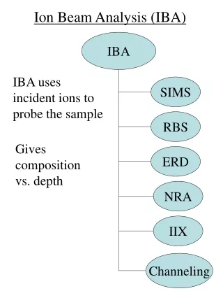
16. Ion beams can be used for sputtering or ion beam etching and for ion beam analysis.
Ion beam etching, or sputtering, is a technique conceptually similar to sandblasting, but using individual atoms in an ion beam to ablate a target.
Reactive ion etching is an important extension that uses chemical reactivity to enhance the physical sputtering effect.
17. In a typical use in semiconductor manufacturing, a mask is used to selectively expose a layer of photoresist on a substrate such as a silicon dioxide or gallium arsenide wafer.
The wafer is developed, and for a positive photoresist, the exposed portions are removed in a chemical process.
The result is a pattern left on the surface areas of the wafer that had been masked from exposure.
18. The wafer is then placed in a vacuum chamber, and exposed to the ion beam.
The impact of the ions erodes the target, abrading away the areas not covered by the photoresist.
This method is frequently enhanced by bleeding a reactive gas into the vacuum system, which is known as reactive ion etching.
19. Focused Ion Beam (FIB) In addition to milling, it is also possible to use the ion beam to force the deposit of new conductive lines on the surface of the device.
This is accomplished by injecting chemicals into the ion stream near the device surface.
The interaction between the ions and the chemicals result in chemical deposition on the surface.
This process is typically referred to as a FIB deposit operation.
In addition to milling, it is also possible to use the ion beam to force the deposit of new conductive lines on the surface of the device.
This is accomplished by injecting chemicals into the ion stream near the device surface.
The interaction between the ions and the chemicals result in chemical deposition on the surface.
This process is typically referred to as a FIB deposit operation.
20. Sputtering Sputtering which is observed to occur below the threshold energy of physical sputtering, is also often called chemical sputtering.
The mechanisms behind such sputtering are not always well understood, and may be hard to distinguish from chemical etching.
At elevated temperature chemical sputtering of carbon can be understood to be due to the incoming ions weakening bonds in the sample, which then desorbs by thermal activation.
The hydrogen-induced sputtering of carbon-based materials observed at low temperatures has been explained by H ions entering between C-C bonds and thus breaking them, a mechanism dubbed swift chemical sputtering.
Sputtering which is observed to occur below the threshold energy of physical sputtering, is also often called chemical sputtering.
The mechanisms behind such sputtering are not always well understood, and may be hard to distinguish from chemical etching.
At elevated temperature chemical sputtering of carbon can be understood to be due to the incoming ions weakening bonds in the sample, which then desorbs by thermal activation.
The hydrogen-induced sputtering of carbon-based materials observed at low temperatures has been explained by H ions entering between C-C bonds and thus breaking them, a mechanism dubbed swift chemical sputtering.
22. - Ion-beam Etching Removing atoms by sputtering with an inert gas is called �ion milling� or �ion etching�.
Sputtering can also play a role in reactive ion etching (RIE), a plasma process carried out with chemically active ions and radicals, for which the sputtering yield may be enhanced significantly compared to pure physical sputtering. Reactive ions are frequently used in SIMS equipment to enhance the sputter rates.
The mechanisms causing the sputtering enhancement are not always well understood, but for instance the case of fluorine etching of Si has been modeled well theoretically.
Reactive ions are frequently used in SIMS equipment to enhance the sputter rates.
The mechanisms causing the sputtering enhancement are not always well understood, but for instance the case of fluorine etching of Si has been modeled well theoretically.
23. - Ion-beam supttering As the ions leave the source they are neutralized by electrons from a second external filament.
IBS has an advantage in that the energy and flux of ions can be controlled independently.
Since the flux that strikes the target is composed of neutral atoms, either insulating or conducting targets can be sputtered.
IBS has found application in the manufacture of thin-film heads for disk drives.
A pressure gradient between the ion source and the sample chamber is generated by placing the gas inlet at the source and shooting through a tube in into the sample chamber. This saves gas and reduces contamination in UHV applications.
The principal drawback of IBS is the large amount of maintenance required to keep the ion source operating.
As the ions leave the source they are neutralized by electrons from a second external filament.
IBS has an advantage in that the energy and flux of ions can be controlled independently.
Since the flux that strikes the target is composed of neutral atoms, either insulating or conducting targets can be sputtered.
IBS has found application in the manufacture of thin-film heads for disk drives.
A pressure gradient between the ion source and the sample chamber is generated by placing the gas inlet at the source and shooting through a tube in into the sample chamber. This saves gas and reduces contamination in UHV applications.
The principal drawback of IBS is the large amount of maintenance required to keep the ion source operating.
24. Ion-Beam sculpting is a term used to describe a two-step process to make solid-state nanopores.
The term itself was coined by Golovchenko and co-workers at Harvard in the paper "Ion-beam sculpting at nanometer length scales".
The term refers to the fact that solid-state nanopores are formed by lateral mass transport about the surface of the substrate, not simply by sputtering which refers to the removal of material from the surface.
25. The first step in ion sculpting is to make either a through hole or a blind hole, most commonly using an focused ion beam (FIB).
The holes are commonly ~100nm, but can be made much smaller.
This step may or may not be done at room temperature, with a low temperature of -120?.
Next, there are three common techniques to now 'sculpt' the hole: broad area ion exposure, TEM exposure, and FIB exposure. Holes can be closed completely, but also they can be left open at a lower limit of 1-10nm.
26. This technique uses a broad area argon ion source beam.
If the hole is blind,the wafer (often SiN or silicon oxide) is then turned upside down, and exposed with the argon beam.
A detector counts the amount of ions passing through the membrane (which should be zero).
The process stops when ions begin to be detected. This enables for a much smaller hole to be opened than if using an FIB alone.
This method of nanopores fabrication relies on the ion beam to remove (sputter) some of the material from the backside of the sample, revealing part of the hole underneath.
Alternatively, if the hole has already been milled through the substrate, the argon beam is aimed at the wafer, and by lateral mass transport atoms from elsewhere on the wafer move to the edge of the hole.
It is this process of solid-state nanopores fabrication that was originally termed "ion-beam sculpting".
The process is stopped when the final pore size is reached. If the current drops to zero, then the hole is closed.
Recently this method has been demonstrated to occur with all the noble gases, not just argon.
Of paramount importance in this method is the ability to utilize a feedback controlled system to monitor nanopores fabrication in real time.
A detector registers the number of ions passing through the hole as a function of time.
As the hole closes from ~100nm to its final dimension (>20nm) the number of ions able to pass through the hole is reduced.
This enables for a much smaller hole to be opened than if using an FIB alone.
This method of nanopores fabrication relies on the ion beam to remove (sputter) some of the material from the backside of the sample, revealing part of the hole underneath.
Alternatively, if the hole has already been milled through the substrate, the argon beam is aimed at the wafer, and by lateral mass transport atoms from elsewhere on the wafer move to the edge of the hole.
It is this process of solid-state nanopores fabrication that was originally termed "ion-beam sculpting".
The process is stopped when the final pore size is reached. If the current drops to zero, then the hole is closed.
Recently this method has been demonstrated to occur with all the noble gases, not just argon.
Of paramount importance in this method is the ability to utilize a feedback controlled system to monitor nanopores fabrication in real time.
A detector registers the number of ions passing through the hole as a function of time.
As the hole closes from ~100nm to its final dimension (>20nm) the number of ions able to pass through the hole is reduced.
27. A through hole in a wafer can be closed down by a transmission electron microscope.
Due to hydrocarbon buildup, the electrons stimulate hole closure.
This method is very slow (taking over an hour to close a 100 nm hole).
The slow method allows for great control of the hole size (since you can watch the hole decrease), but its drawback is that it takes a long time.
28. The use of IBM for smoothing of laser mirrors and for modifying the thickness of thin films and membranes without affecting surface finish is reported by Jolly, and Reader.
29. Hudson has demonstrated that an ion-beam source is a controlled method for texturing surfaces.
A typical result is presented which a structure resembling closely packed cones was produced.
As well as the nickel and copper, Hudson went on to investigate 26 materials, including stainless steel, silver and gold. He has also summarized a number of other investigations in which a microscopic surface texture is created by sputter-etching performed simultaneously with the sputter-deposition of a lower yield material onto the surface.
Applications of ion beam texturing have been discussed further by Jolly et al.
They include enhanced bonding of surfaces increased surface areas of capacitors and surface treatment of medical implants.
He has also summarized a number of other investigations in which a microscopic surface texture is created by sputter-etching performed simultaneously with the sputter-deposition of a lower yield material onto the surface.
Applications of ion beam texturing have been discussed further by Jolly et al.
They include enhanced bonding of surfaces increased surface areas of capacitors and surface treatment of medical implants.
30. Atomically clean surfaces can be produced by IBM.
This technique can be preferable to electron beam and electrical discharge methods which can damage the surface.
Harper, Cuomo and Kaufman discuss in detail this well-established application of ion beam technology. For example, they report substantial improvements in the adhesion of gold films to silicon and aluminum oxide Al2O3 substrates by use of argon or oxygen ion beam sputter-cleaning of the substrate, prior to evaporation.
The cleaning consisted mainly of removal of absorbed water and hydrocarbons.
When a laser of surface oxide has to be removed in order to clean a surface, higher ion energies, of several hundred ev are needed.
Damage to the substrate material may then arise: in this case a reactive gas with high selectivity of oxide etching can be used.
For example, they report substantial improvements in the adhesion of gold films to silicon and aluminum oxide Al2O3 substrates by use of argon or oxygen ion beam sputter-cleaning of the substrate, prior to evaporation.
The cleaning consisted mainly of removal of absorbed water and hydrocarbons.
When a laser of surface oxide has to be removed in order to clean a surface, higher ion energies, of several hundred ev are needed.
Damage to the substrate material may then arise: in this case a reactive gas with high selectivity of oxide etching can be used.
31. Thinning by use of oblique incidence argon ions has been used to enhance polishing.
Macroscopic thinning and shaping of materials can be applied to the fabrication of magnetic heads and surface acoustic wave devices. Taniguchi points out that these operations are performed by the direct sputtering of performs in glass silica and diamond.
Unlike conventional technology involving cutting, grinding, lapping and polishing, the ion beam process has no inherent polishing surface, e.g. guide ways, the reference being the perform or patterning mask.
Thinning of samples of silicon to a thickness of 10 to 15�m has been obtained by argon ions impinging at normal incidence.
The production of samples for transmission electron microscopy (TEM) is another widespread practice; two opposing beams thin a circular region on a rotating sample until the centre etches through, leaving thin fringe areas suitable for TEM.
Taniguchi points out that these operations are performed by the direct sputtering of performs in glass silica and diamond.
Unlike conventional technology involving cutting, grinding, lapping and polishing, the ion beam process has no inherent polishing surface, e.g. guide ways, the reference being the perform or patterning mask.
Thinning of samples of silicon to a thickness of 10 to 15�m has been obtained by argon ions impinging at normal incidence.
The production of samples for transmission electron microscopy (TEM) is another widespread practice; two opposing beams thin a circular region on a rotating sample until the centre etches through, leaving thin fringe areas suitable for TEM.
35. Ion milling is especially useful for the accurate production of shallow grooves.
Milling through masks to produce regular arrays of pits with widths of 5 to 200�m and depths of up to 1mm for enhanced bonding.
Pillar-like configurations useful in the manufacture of precision electrical resistive and fiber optic arrays can be produced by ion beam methods. Other workers have also confirmed the usefulness of ion milling techniques as an alternative to the fabrication by chemical etching of devices of fine geometry.
The latter technique is limited to line widths of above 2�m, and 1:1 depth-to-width ratios.
IBM offers an alternative method which is limited only by masking capabilities.
For example, line widths of 0.2�m have been achieved by IBM in the fabrication of bubble memory devices; depth-to-width ratios 2:1 have been achieved.
Problems associated with chemical etching, such as lack of line delineation owing to failure of resist adhesion and undercutting of layers, are avoided since masking is only needed to shadow the beam.
Other workers have also confirmed the usefulness of ion milling techniques as an alternative to the fabrication by chemical etching of devices of fine geometry.
The latter technique is limited to line widths of above 2�m, and 1:1 depth-to-width ratios.
IBM offers an alternative method which is limited only by masking capabilities.
For example, line widths of 0.2�m have been achieved by IBM in the fabrication of bubble memory devices; depth-to-width ratios 2:1 have been achieved.
Problems associated with chemical etching, such as lack of line delineation owing to failure of resist adhesion and undercutting of layers, are avoided since masking is only needed to shadow the beam.
39. Ion implantation is a material engineering process by which ions of a material can be implanted into another solid, thereby changing the physical properties of the solid.
Ion implantation is used in semiconductor device fabrication and in metal finishing, as well as various applications in materials science research.
40. Ion implantation equipment typically consists of an ion source, where ions of the desired element are produced, an accelerator, where the ions are electrostatically accelerated to a high energy, and a target chamber, where the ions impinge on a target, which is the material to be implanted.
41. - Ion implantation Typical ion energies are in the range of 10 to 500keV.
Energies in the range 1 to 10keV can be used, but result in a penetration of only a few nanometers or less.
Energies lower than this result in very little damage to the target, and fall under the designation ion beam deposition.
Higher energies can also be used: accelerators capable of 5MeV are common.
42. The energy of the ions, as well as the ion species and the composition of the target determine the depth of penetration of the ions in the solid:
A mono-energetic ion beam will generally have a broad depth distribution.
The average penetration depth is called the range of the ions.
Under typical circumstances ion ranges will be between 10 nanometers and 1 micrometer.
44. - Doping The introduction of dopants in a semiconductor is the most common application of ion implantation.
Dopant ions such as boron, phosphorus or arsenic are generally created from a gas source, so that the purity of the source can be very high.
These gases tend to be very hazardous.
45. One prominent method for preparing silicon on insulator (SOI) substrates from conventional silicon substrates is the SIMOX process, wherein a buried high dose oxygen implant is converted to silicon oxide by a high temperature annealing process.
46. Mesotaxy is the term for the growth of a crystallographically matching phase underneath the surface of the host crystal (compare to epitaxy, which is the growth of the matching phase on the surface of a substrate).
In this process, ions are implanted at a high enough energy and dose into a material to create a layer of a second phase, and the temperature is controlled so that the crystal structure of the target is not destroyed.
47. Nitrogen or other ions can be implanted into a tool steel target.
The structural change caused by the implantation produces a surface compression in the steel, which prevent crack propagation and thus makes the material more resistant to fracture.
The chemical change can also make the tool more resistant to corrosion.
48. Ion implantation is used in such cases to engineer the surfaces of such devices for more reliable performance.
As in the case of tool steels, the surface modification caused by ion implantation includes both a surface compression which prevents crack propagation and an alloying of the surface to make it more chemically resistant to corrosion.
49. Vacancies and Interstitials.
Vacancies are crystal lattice points unoccupied by an atom: in this case the ion collides with a target atom, resulting in transfer of a significant amount of energy to the target atom such that it leaves its crystal site.
Interstitials result when such atoms (or the original ion itself) come to rest in the solid, but find no vacant space in the lattice to reside.
50. Because ion implantation causes damage to the crystal structure of the target which is often unwanted, ion implantation processing is often followed by a thermal annealing.
This can be referred to as damage recovery.
51. In some cases, complete amorphization of a target is preferable to a highly defective crystal.
An amorphized film can be regrown at a lower temperature than required to anneal a highly damaged crystal.
52. Some of the collision events result in atoms being ejected (sputtered) from the surface, and thus ion implantation will slowly etch away a surface.
The effect is only appreciable for very large doses.
53. If there is a crystallographic structure to the target and especially in semiconductor substrates where the crystal structure is more open, particular crystallographic directions offer much lower stopping than other directions.
The result is that the range of an ion can be much longer if the ion travels exactly along a particular direction, for example the <110> direction in silicon and other diamond cubic materials.
This effect is called ion channeling.
54. The toxic materials used in the ion implanter process.
Such hazardous elements, solid source and gasses are used, such as Arsine and Phosphine .
Other elements may include Antimony, Arsenic, Phosphorus, and Boron.
It is important not to expose yourself to these carcinogenic, corrosive, flammable, and toxic elements.
55. High voltage power supplies in ion implantation equipment can pose a risk of electrocution.
In addition, high-energy atomic collisions can generate radionuclides.
Prior to entry to high voltage area, terminal components must be grounded using a grounding stick.
56. Advantages of IBM Low temperature processing reduces handling an stress problems.
No dimensional changes
Good adhesion of treated surface
New alloys possible
Can improve corrosion, oxidation, wear, hardness, friction, fatigue
57. Disadvantages of IBM Very shallow treatment (< 1 �m)
High cost
The surface can be weakened by radiation effects
58. Applications of IBM Nitrogen implantation has been used to increase wear resistance and give longer life,
injection molding screws
high speed steel tools
a clutch housing tool
hip prosthesis
Yttrium gives oxidation and wear resistance
Titanium and carbon on iron gives lower friction and better wear.
Chromium is used to maintain strength of holes.