Download
1 / 9
100 likes | 298 Vues
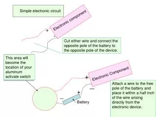
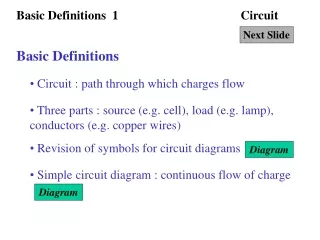
SPH3U Simple Circuit. Start with a simple electric circuit, with a 6.0 V battery source and a single 10 W resistor. The 6.0 V battery has 2 terminals: +3.0 V and -3.0 V. The voltage (potential difference) between the two terminals is 6.0 V. .

E N D
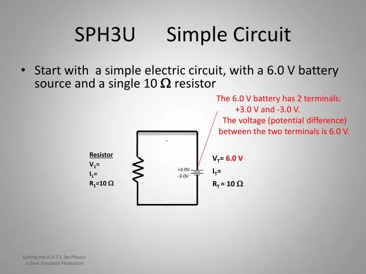
SPH3U Simple Circuit • Start with a simple electric circuit, with a 6.0 V battery source and a single 10 W resistor The 6.0 V battery has 2 terminals: +3.0 V and -3.0 V. The voltage (potential difference) between the two terminals is 6.0 V. • Resistor V1= I1= R1=10 W VT= 6.0 V IT= • RT = 10 W +3.0V -3.0V Getting the H.O.T.S. for Physics a Dave Doucette Production
SPH3U Simple Circuit • Start with a simple electric circuit, with a 6.0 V battery source and a single 10 W resistor This conducting wire has a voltage of +3.0V The 6.0 V battery has 2 terminals: +3.0 V and -3.0 V +3.0V +3.0V +3.0V • Resistor V1= I1= R1=10 W VT= 6.0 V IT= • RT = 10 W +3.0V -3.0V -3.0V -3.0V -3.0V This conducting wire has a voltage of -3.0 V Getting the H.O.T.S. for Physics a Dave Doucette Production
SPH3U Simple Circuit • Start with a simple electric circuit, with a 6.0 V battery source and a single 10 W resistor This conducting wire has a voltage of +3.0V The 6.0 V battery has 2 terminals: +3.0 V and -3.0 V +3.0V +3.0V +3.0V • Resistor V1= I1= R1=10 W 6.0 V VT= 6.0 V IT= • RT = 10 W 6.0 V/10 W = 0.60 A 0.60 A +3.0V -3.0V -3.0V -3.0V -3.0V This conducting wire has a voltage of -3.0 V Getting the H.O.T.S. for Physics a Dave Doucette Production
SPH3U Series Circuit • Now we add a second 10 W resistor in series • Resistor 2 V1= I1= R1=10 W This conducting wire is midway between +3.0 V and -3.0 V, ie,0.0 V. 3.0 V This conducting wire has a voltage of +3.0V +3.0V 0.0 V +3.0V • Resistor 1 V1= I1= R1=10 W VT= 6.0 V IT= • RT = 20 W 3.0 V 6.0 V/20 W = 0.30 A 0.30 A 0.30 A +3.0V -3.0V -3.0V -3.0V -3.0V This conducting wire still has a voltage of -3.0 V Getting the H.O.T.S. for Physics a Dave Doucette Production
SPH3U Series Circuit • Let us look at this circuit again – in terms of the potential differences across the source and the resistors The voltage across resistor 1 is 3.0 V 3.0 V = + 0.0 V +3.0V +3.0V The voltage across resistor 2 is 3.0 V 3.0 V The voltage across the source is 6.0 V +3.0V 6.0 V -3.0V -3.0V -3.0V -3.0V The sum of the potential differences across the resistors equals the potential difference across the source. This occurs due to the distribution of surface charge. Getting the H.O.T.S. for Physics a Dave Doucette Production
SPH3U Series Circuit • Now we add a third 10 W resistor in series • Resistor 2 V1= I1= R1=10 W This conducting wire has a voltage of +1.0V 2.0 V This conducting wire Still has a voltage of +3.0V +3.0V +1.0V +3.0V • Resistor 1 V1= I1= R1=10 W VT= 6.0 V IT= • RT = 30 W 2.0 V 6.0 V/30 W = 0.20 A 0.20 A 0.20 A 0.20 A +3.0V -3.0V -3.0V This conducting wire has a voltage of -1.0V -1.0V -3.0V This conducting wire still has a voltage of -3.0 V • Resistor 3 V1= I1= R1=10 W 2.0 V Getting the H.O.T.S. for Physics a Dave Doucette Production
SPH3U Series Circuit • Let us look at this circuit again – in terms of the potential differences across the source and the resistors The voltage across resistor 1 is 2.0 V 2.0 V = + + +3.0V +1.0V +3.0V The voltage across resistor 2 is 2.0 V 2.0 V The voltage across the source is 6.0 V +3.0V 6.0 V -3.0V -3.0V -1.0V -3.0V The voltage across resistor 3 is 2.0 V 2.0 V Getting the H.O.T.S. for Physics a Dave Doucette Production
Part 2 Potential Difference & Parallel Circuits
SPH3U Parallel Circuit • Start with a 12 V battery source and two 8.0 W resistors, in a parallel circuit: These conducting wires have a voltage of +6.0 V The 12V battery has 2 terminals: +6.0 V and -6.0 V. The voltage (potential difference) between the two terminals is 12V. +6.0 V +6.0 V +6.0 V • Resistor 1 V1= I1= R1=8.0 W • Resistor 2 V2= I2= R2=8.0 W VT= 12V • IT= 12V / 4.0 W = 3.0 A • RT = _______1_____ = 4.0 W 1/8.0 + 1/8.0 12 V 12 V +6.0V 1.5 A 1.5 A -6.0 V -6.0 V -6.0 V -6.0 V These conducting wires have a voltage of +6.0 V Getting the H.O.T.S. for Physics a Dave Doucette Production