Download
1 / 45
450 likes | 569 Vues
NSTX. Supported by. HHFW Heating and Current Drive Studies of NSTX H-Mode Plasmas*. Gary Taylor 1

E N D
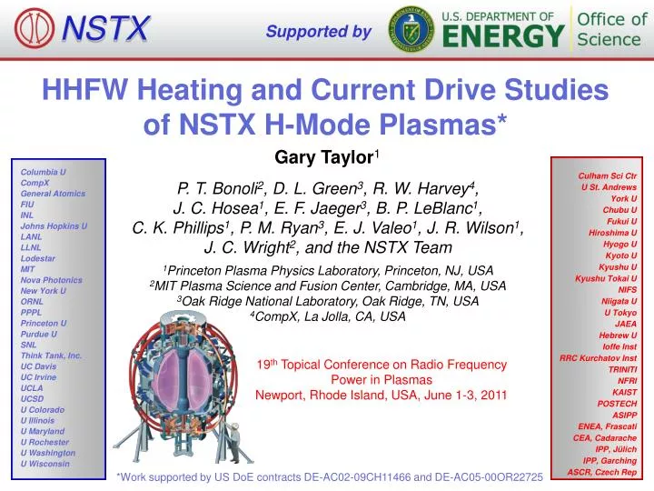
NSTX Supported by HHFW Heating and Current Drive Studies of NSTX H-Mode Plasmas* Gary Taylor1 P. T. Bonoli2, D. L. Green3, R. W. Harvey4, J. C. Hosea1, E. F. Jaeger3, B. P. LeBlanc1, C. K. Phillips1, P. M. Ryan3, E. J. Valeo1, J. R. Wilson1, J. C. Wright2, and the NSTX Team 1Princeton Plasma Physics Laboratory, Princeton, NJ, USA 2MIT Plasma Science and Fusion Center, Cambridge, MA, USA 3Oak Ridge National Laboratory, Oak Ridge, TN, USA 4CompX, La Jolla, CA, USA Culham Sci Ctr U St. Andrews York U Chubu U Fukui U Hiroshima U Hyogo U Kyoto U Kyushu U Kyushu Tokai U NIFS Niigata U U Tokyo JAEA Hebrew U Ioffe Inst RRC Kurchatov Inst TRINITI NFRI KAIST POSTECH ASIPP ENEA, Frascati CEA, Cadarache IPP, Jülich IPP, Garching ASCR, Czech Rep Columbia U CompX General Atomics FIU INL Johns Hopkins U LANL LLNL Lodestar MIT Nova Photonics New York U ORNL PPPL Princeton U Purdue U SNL Think Tank, Inc. UC Davis UC Irvine UCLA UCSD U Colorado U Illinois U Maryland U Rochester U Washington U Wisconsin 19th Topical Conference on Radio Frequency Power in Plasmas Newport, Rhode Island, USA, June 1-3, 2011 *Work supported by US DoE contracts DE-AC02-09CH11466 and DE-AC05-00OR22725
Outline • Introduction to HHFW Heating on NSTX • HHFW-Generated H-Mode Plasmas • HHFW Heating of NBI H-Mode Plasmas • Summary
Outline • Introduction to HHFW Heating on NSTX • HHFW-Generated H-Mode Plasmas • HHFW Heating of NBI H-Mode Plasmas • Summary
Outline • Introduction to HHFW Heating on NSTX • HHFW-Generated H-Mode Plasmas • HHFW Heating of NBI H-Mode Plasmas • Summary
Outline • Introduction to HHFW Heating on NSTX • HHFW-Generated H-Mode Plasmas • HHFW Heating of NBI H-Mode Plasmas • Summary
NSTX is a high b, low aspect ratio, spherical torus with both 90 keV NBI and 30 MHz HHFW heating • R = 0.86 m • A > 1.27 • Ip < 1.5 MA • Bt(0) = 0.55 T • bt ≤ 40%, bN ≤ 7 • 90 keV D PNBI ≤ 6 MW • 30 MHz PRF ≤ 6 MW • Many fast wave ion resonances: 7-11 WD • Strong single pass direct absorption on electrons
Well defined antenna spectrum, ideal for studying phase dependence of heating & current drive (CD) 30 MHz Power Sources 5 Port Cubes Decoupler Elements 12 Antenna Straps B IP 12-strap antenna extends toroidally 90° • Upgraded from single to double feed straps, with center grounds, in 2009 to reduce electric fields near Faraday shield ~ 1.5 x for same strap currents P. M. Ryan, et al., Poster A32
HHFW heating and CD are being developed for non-inductive ramp-up and bulk electron heating Non-Inductive Strategy IP [kA] • Two major roles for HHFW heating and CD in NSTX: • Enable fully non-inductive plasma current (Ip) ramp-up through bootstrap CD (BSCD) and direct RFCD during early HHFW H-mode • Provide bulk electron heating during Ip flat top, during NBI H-Mode ~ 750 ~ 500 ~ 300 H-mode Time HHFW + NBI HHFW Sustain with HHFW + NBI CHI, PF, Guns
NSTX HHFW research in 2008-10 focused on studying both HHFW-Generated H-Modes & HHFW-Heated NBI H-modes • Near-term approach to assess HHFW heating during Ip ramp-up has been to heat low Ip ohmic (~ 300 kA) plasmas to access 100% non-inductive CD • Improved antenna/plasma conditioning produced HHFW-generated H-mode plasmas with Ip = 650 kA, BT(0) = 0.55 T when PRF ≥ 2.5 MW • NBI + HHFW H-mode experiments at Ip = 0.7 - 1 MA, aided by Li conditioning, produced significant bulk electron heating when HHFW was coupled into the plasma: • HHFW acceleration of NBI fast-ions produced enhanced fast-ion losses during HHFW heating • Conducted extensive studies of HHFW heating and edge power loss mechanisms during ELMing and ELM-free H-modes
NSTX HHFW research in 2008-10 focused on studying HHFW-Generated H-Modes & HHFW-Heated NBI H-modes • Near-term approach to assess HHFW heating during Ip ramp-up has been to heat low Ip ohmic (~ 300 kA) plasmas to access 100% non-inductive CD • Improved antenna/plasma conditioning produced HHFW-generated H-mode plasmas with Ip = 650 kA, BT(0) = 0.55 T when PRF ≥ 2.5 MW • NBI + HHFW H-mode experiments at Ip = 0.7 - 1 MA, aided by Li conditioning, produced significant bulk electron heating when HHFW was coupled into the plasma: • HHFW acceleration of NBI fast-ions produced enhanced fast-ion losses during HHFW heating • Conducted extensive studies of HHFW heating and edge power loss mechanisms during ELMing and ELM-free H-modes
NSTX HHFW research in 2008-10 focused on studying HHFW-Generated H-Modes & HHFW-Heated NBI H-modes • Near-term approach to assess HHFW heating during Ip ramp-up has been to heat low Ip ohmic (~ 300 kA) plasmas to access 100% non-inductive CD • Improved antenna/plasma conditioning produced HHFW-generated H-mode plasmas with Ip = 650 kA, BT(0) = 0.55 T when PRF ≥ 2.5 MW • NBI + HHFW H-mode experiments at Ip = 0.7 - 1 MA, aided by Li conditioning, produced significant bulk electron heating when HHFW was coupled into the plasma: • HHFW acceleration of NBI fast-ions produced enhanced fast-ion losses during HHFW heating • Conducted extensive studies of HHFW heating and edge power loss mechanisms during ELMing and ELM-free H-modes
NSTX HHFW research in 2008-10 focused on studying HHFW-Generated H-Modes & HHFW-Heated NBI H-modes • Near-term approach to assess HHFW heating during Ip ramp-up has been to heat low Ip ohmic (~ 300 kA) plasmas to access 100% non-inductive CD • Improved antenna/plasma conditioning produced HHFW-generated H-mode plasmas with Ip = 650 kA, BT(0) = 0.55 T when PRF ≥ 2.5 MW • NBI + HHFW H-mode experiments at Ip = 0.7 - 1 MA, aided by Li conditioning, produced significant bulk electron heating when HHFW was coupled into the plasma: • HHFW acceleration of NBI fast-ions produced enhanced fast-ion losses during HHFW heating • Conducted extensive studies of HHFW heating and edge power loss mechanisms during ELMing and ELM-free H-modes
NSTX HHFW research in 2008-10 focused on studying HHFW-Generated H-Modes & HHFW-Heated NBI H-modes • Near-term approach to assess HHFW heating during Ip ramp-up has been to heat low Ip ohmic (~ 300 kA) plasmas to access 100% non-inductive CD • Improved antenna/plasma conditioning produced HHFW-generated H-mode plasmas with Ip = 650 kA, BT(0) = 0.55 T when PRF ≥ 2.5 MW • NBI + HHFW H-mode experiments at Ip = 0.7 - 1 MA, aided by Li conditioning, produced significant bulk electron heating when HHFW was coupled into the plasma: • HHFW acceleration of NBI fast-ions produced enhanced fast-ion losses during HHFW heating • Conducted extensive studies of HHFW heating and edge power loss mechanisms during ELMing and ELM-free H-modes
Non-Inductive Strategy IP [kA] HHFW-Generated H-Mode Plasmas ~ 750 ~ 500 ~ 300 H-mode Time HHFW + NBI HHFW Sustain with HHFW + NBI CHI, PF, Guns
Achieved sustained Ip = 300 kA HHFW H-mode, with internal transport barrier (ITB) and Te(0) = 3 keV with PRF = 1.4 MW • In 2005 could not maintain RF coupling during Ip = 250 kA HHFW H-mode due to poor plasma position control at L-H transitions • Sustained HHFW H-mode at Ip = 300 kA in 2010 made possible by reduced plasma control system latency: • ITB formed during H-mode • Positive feedback between ITB, high Te(0) and RF CD Ip = 300 kA BT(0) = 0.55 T Deuterium kf = - 8 m-1 Te(0) 3 keV Time of GENRAY-ADJ analysis
GENRAY-ADJ predicts peaked RF deposition on electrons and RF CD efficiency xCD ~ 115 kA/MW Shot 138506 Time = 0.382 s IP = 300 kA BT = 5.5 kG Deuterium RF H-mode r/a IRFCD ~ 115 kA/MW GENRAY/ADJ-QL r/a
TRANSP-TORIC simulation, assuming 100% RF coupling (heff = 100%), predicts IBootstrap = 220 kA and IRF = 120 kA TORIC-TRANSP modeling for heff = 100% Time of GENRAY-ADJ analysis • TRANSP-TORIC predicts xCD~ 85 kA/MW at GENRAY analysis time: • Compared to GENRAY xCD~ 115 kA/MW • heff = DWT/(t*PRF) • DWT ~ 13 kJ • t ~ 15 ms • PRF~ 1.4 MW • heff ~ 60%
80% of the non-inductive current is generated inside the ITB in the Ip = 300 kA HHFW H-mode TORIC-TRANSP modeling for heff = 100% For heff = 60% • New Motional Stark Effect – Laser Induced Fluorescence (MSE-LIF) diagnostic will provide current profile measurements during HHFW H-modes
Improved antenna conditioning produced ELM-free-like HHFW H-modes at Ip = 650 kA with PRF ≥ 2.5 MW He, kf = - 8 m-1 Ip = 650 kA, BT(0) = 0.55 T • Substantial increase in stored energy during H-mode • Stored energy increase is accompanied by edge oscillations and small ELMs • Sustained Te(0) = 5 - 6 keV
Very broad RF electron power deposition profile (Qe) andoff-axis trapping in H-mode significantly reduces xCD PRF = 1 MW GENRAY-ADJ GENRAY-ADJ Ip = 650 kA, BT(0) = 0.55 T Helium kf = - 8 m-1 • RF power coupled to plasma directly heats electrons, no ion heating • xCD~ 220 kA/MW in L-Mode, xCD~ 130 kA/MW in H-Mode
IRFCD and IBootstrap decline as the plasma slowly transitions from L-Mode to H-Mode TORIC-TRANSP modeling for heff = 100% Times of GENRAY-ADJ analysis L-mode H-mode PRF = 2.7 MW
fNI decreases from ~ 0.5 in L-mode to ~ 0.35 in H-mode as Pe(R) broadens & RF deposition moves more off-axis TORIC-TRANSP modeling for heff = 100% • DWT ~ 25 kJ, t ~ 17 ms heff ~ 55% For heff = 55%
Non-Inductive Strategy IP [kA] HHFW Heating of NBI H-Mode Plasmas ~ 750 ~ 500 ~ 300 H-mode Time HHFW + NBI HHFW Sustain with HHFW + NBI CHI, PF, Guns
Broad Te profile increase with kf = -13 m-1 HHFW heating of Ip = 900 kA, BT(0) = 0.55 T, Deuterium NBI H-mode plasma BeforeHHFW Heating PRF = 1.9 MW PNBI = 2 MW DuringHHFW Heating • Identical Te and ne H-mode profiles before HHFW power onset • During HHFW heating, ne profile remains unchanged and plasma stayed in H-mode
TRANSP-TORIC analysis predicts ~ 50% of PRF leaving antenna is coupled to Ip = 900 kA ELM-free NBI H-mode plasma • Fraction of PRF absorbed within LCFS (heff) obtained from TRANSP-calculated electron stored energy: WeX – from HHFW+NBI H-mode WeR – from matched NBI H-mode WeP– using e from NBI H-mode to predict Te in HHFW+NBI H-mode • heff =(WeX-WeR)/(WeP-WeR) = 0.53 ± 0.07 • TORIC used to calculate the power absorbed by electrons (PeP) assuming 100% RF plasma absorption • Electron absorption, PeA= heff × PeP For PRF = 1.9 MW: • 0.7 MW electrons • 0.3 MW ions • fNI ~ 0.3 (IBootstrap = 180 kA, [IRFCD+INBICD] = 60 kA) k|| = -13 m-1
GENRAY ray tracing analysis predicts broad deposition, with very little RF power reaching magnetic axis GENRAY For 1 MW of Coupled RF Power Deuterium kf = - 13 m-1 Ip = 900 kA BT(0) = 0.55 T • 75% of RF power directly heats electrons • 25% of RF power accelerates NBI fast-ions, predominantly well off axis • GENRAY deposition results similar to TRANSP-TORIC
CQL3D Fokker-Planck code predicts significant fast-ion losses in Ip = 900 kA ELM-free HHFW+NBI H-mode • Without fast-ion loss CQL3D predicts much higher neutron production rate (Sn) than is measured • Simple-banana-loss model predicts Sn ~ 20% below measured Sn : • Assumes prompt loss of fast-ions with a gyro radius+ banana width > distance to LCFS • ~ 60% RF power to fast-ions is promptly lost • Significant prompt fast-ion loss is due toRF wave-field acceleration occurringpredominantly off-axis
HHFW+NBI H-modes can exhibit a significant RF power flow in the scrape-off layer (SOL) to the lower divertor • RF power flow produces local hot region on divertor plate that moves with changes in the magnetic field pitch • ELMs increase RF power flow to the divertor J. C. Hosea, et al., Poster A33
AORSA simulations of NBI+HHFW H-modes predict large amplitude coaxial modes at long launch wavelengths • Large amplitude, non-propagating coaxial modes form in SOL can dissipate significant RF power if collisionally damped AORSA full wave simulation of NBI+HHFW H-mode PRF=1.9 MW PNBI = 2 MW Ip = 1 MA BT(0) = 0.55 T 130608 @ 0.353 ms D. L. Green, et al., Poster A36
Summary • Generated HHFW-only "ELM-free-like" H-modes that have rising Wtot, high Te(0), fNI up to 0.65, and sometimes ITBs • Improved antenna & plasma conditioning enabled a broad increase in Te(R) when HHFW was coupled to an ELM-free NBI-generated H-mode • A significant RF power flow along field lines in the SOL produced a hot region on the lower divertor plate that moves with change in field pitch • 3-D simulations that include the SOL predict modes in the SOL and plasma edge that appear qualitatively similar to observed RF power flow • Similar edge/SOL RF power flows may be important in ITER NBI+ICRF H-mode scenarios, these need to be modeled with advanced RF codes
Summary • Generated HHFW-only "ELM-free-like" H-modes that have rising Wtot, high Te(0), fNI up to 0.65, and sometimes ITBs • Improved antenna & plasma conditioning enabled a broad increase in Te(R) when HHFW was coupled to an ELM-free NBI-generated H-mode • A significant RF power flow along field lines in the SOL produced a hot region on the lower divertor plate that moves with change in field pitch • 3-D simulations that include the SOL predict modes in the SOL and plasma edge that appear qualitatively similar to observed RF power flow • Similar edge/SOL RF power flows may be important in ITER NBI+ICRF H-mode scenarios, these need to be modeled with advanced RF codes
Summary • Generated HHFW-only "ELM-free-like" H-modes that have rising Wtot, high Te(0), fNI up to 0.65, and sometimes ITBs • Improved antenna & plasma conditioning enabled a broad increase in Te(R) when HHFW was coupled to an ELM-free NBI-generated H-mode • A significant RF power flow along field lines in the SOL produced a hot region on the lower divertor plate that moves with change in field pitch • 3-D simulations that include the SOL predict modes in the SOL and plasma edge that appear qualitatively similar to observed RF power flow • Similar edge/SOL RF power flows may be important in ITER NBI+ICRF H-mode scenarios, these need to be modeled with advanced RF codes
Summary • Generated HHFW-only "ELM-free-like" H-modes that have rising Wtot, high Te(0), fNI up to 0.65, and sometimes ITBs • Improved antenna & plasma conditioning enabled a broad increase in Te(R) when HHFW was coupled to an ELM-free NBI-generated H-mode • A significant RF power flow along field lines in the SOL produced a hot region on the lower divertor plate that moves with change in field pitch • 3-D simulations that include the SOL predict modes in the SOL and plasma edge that appear qualitatively similar to observed RF power flow • Similar edge/SOL RF power flows may be important in ITER NBI+ICRF H-mode scenarios, these need to be modeled with advanced RF codes
Summary • Generated HHFW-only "ELM-free-like" H-modes that have rising Wtot, high Te(0), fNI up to 0.65, and sometimes ITBs • Improved antenna & plasma conditioning enabled a broad increase in Te(R) when HHFW was coupled to an ELM-free NBI-generated H-mode • A significant RF power flow along field lines in the SOL produced a hot region on the lower divertor plate that moves with change in field pitch • 3-D simulations that include the SOL predict modes in the SOL and plasma edge that appear qualitatively similar to observed RF power flow • Similar edge/SOL RF power flows may be important in ITER NBI+ICRF H-mode scenarios, these need to be modeled with advanced RF codes
Summary • Generated HHFW-only "ELM-free-like" H-modes that have rising Wtot, high Te(0), fNI up to 0.65, and sometimes ITBs • Improved antenna & plasma conditioning enabled a broad increase in Te(R) when HHFW was coupled to an ELM-free NBI-generated H-mode • A significant RF power flow along field lines in the SOL produced a hot region on the lower divertor plate that moves with change in field pitch • 3-D simulations that include the SOL predict modes in the SOL and plasma edge that appear qualitatively similar to observed RF power flow • Similar edge/SOL RF power flows may be important in ITER NBI+ICRF H-mode scenarios, these need to be modeled with advanced RF codes
GENRAY ray tracing code calculates the HHFW power deposition and RF-driven current profile • GENRAY is an all-waves general ray tracing code for RF wave propagation and absorption in the geometrical optics approximation • GENRAY outputs ray trajectory and absorption data to other codes • Recently, an all-frequencies, linear, momentum conserving CD calculation has been added to GENRAY (GENRAY/ADJ-QL) • The CD calculation utilizes an adjoint (ADJ) approach based on the relativistic Coulomb Fokker-Planck collision operator and the relativistic quasi-linear (QL) flux
TRANSP-TORIC code provides a time-dependent calculation of the HHFW power deposition and CD profile • TORIC full-wave RF code has been integrated into the TRANSPplasma transport code • TORIC solves the kinetic wave equation in a 2-D axisymmetric equilibrium • Solves for a fixed frequency with a linear plasma response • Present implementation of TORIC in TRANSP can model HHFW deposition but cannot evolve the fast-ion energy distribution self consistently: • As a result, the neutron rate (Sn) calculated by TRANSP-TORIC reflects the beam-target reactions for the NBI fast-ions without HHFW acceleration
CQL3D Fokker-Planck code can predict the RF-driven current and the wave field acceleration of the NBI fast-ions • CQL3D is a relativistic collisional, quasi-linear, 3-D code which solves a bounced-averaged Fokker Planck equation: • Uses the ray trajectories and absorption input from GENRAY to calculate the RF power deposition and CD profile • CQL3D also computes wave field effects on the fast-ions & predicts Sn • Using input data from TRANSP at a particular time-of-interest (TOI), CQL3D can be "run to equilibrium" in order to estimate Sn • CQL3D currently provides two fast-ion loss calculation options: • "No loss" (NL) option, which assumes zero ion gyroradius and banana width • "Simple-banana-loss" (SBL) calculation which assumes that any ion which has a gyroradius + banana width > than the distance to the last closed flux surface (LCFS) is promptly lost
Coupling PRF = 1.4 MW into Ip = 300kA, PNBI = 2 MW H-mode resulted in lower fNI than the Ip = 300kA HHFW H-mode • Density increased during HHFW heating probably due to fast-ion interaction with the antenna • Much lower Te(0) and higher ne(0) than HHFW H-mode resulted in lower IRFCD ~ 10-20 kA • 50% of injected NBI fast-ions are promptly lost at this low Ip • IBootstrap = 60-90 kA, INBICD = 50-70 kA • heff was only ~ 40%: • high nedge ~ 1-2 x10¹² m-3 (ncrit ~ 5x10¹¹m-3), probably caused more surface wave loss 140352/3 140352B04(NBI+RF) 140353B04 (NBI)
40% of coupled RF power accelerates NBI fast-ions which are then promptly lost from the plasma Shot 140352 Time = 0.450 s IP = 300 kA BT = 0.55 T Deuterium HHFW+NBI H-mode IRFCD ~ 20 kA/MW GENRAY/ADJ-QL
HHFW heating of Ip = 300 kA NBI H-mode produces a smallincrease in fNI, due to increased IBootstrap TORIC-TRANSP modeling for heff = 100%: For heff = 40%
HHFW double end-fed upgrade was installed in 2009, shifted ground from end to strap center to increase maximum PRF • Designed to bring system voltage limit with plasma (~15 kV) to limit in vacuum (~25 kV): • Increasing PRF ~ 2.8 times • Antenna upgrade was beneficial: • Reached arc-free PRF ~ 4 MW after a few weeks of operation at the end of 2009 campaign • In 2008-9, Li wall conditioning was observed to enhance HHFW coupling by decreasing edge density Original RF Feeds New Ground New RF Feeds Previous Ground
Fast-ion diagnostic measures no change in fast-ion density during HHFW heating, consistent with CQL3D modeling 134909/10 134909/10
Compare two closely matched Ip = 900 kA ELM-free H-mode plasmas: NBI+HHFW and NBI • IP = 900 kA, BT = 0.55 T, PNBI = 2 MW, PRF = 1.9 MW, k|| = 13 m-1 • Benign MHD activity in both plasmas • MSE q profiles unavailable • Times-of-interest (TOI) 0.248 s and 0.315 s