Download

1 / 55
550 likes | 700 Vues
Voltages that Wiggle. PHY-2054. Alternating Current Part 1. or Back to Trigonometry. We will do the lab session on the inductor’s time constant. We will discuss what happens when the applied voltage is a sinusoid. We will do some experiments on AC circuits We will have a quiz on Friday.

E N D
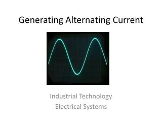
Voltages that Wiggle PHY-2054 Alternating CurrentPart 1
or Back to Trigonometry
We will do the lab session on the inductor’s time constant. We will discuss what happens when the applied voltage is a sinusoid. We will do some experiments on AC circuits We will have a quiz on Friday. NOTE: Start reading chapter 23! – AC Circuits This week
CALENDAR Date and Time of Final is being investigated.
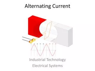
ac generator – Similar to the motor but really different … whatever that means!
y=f(x-2)=(x-2)2 y x2 (x-2)2 2 x
f(x-b): shift a distance b in the POSITIVE direction f(x+b): shift a distance n in the NEGATIVE direction. The signs switch! the “rule”
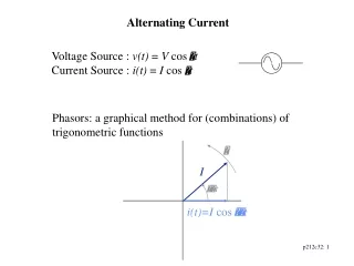
Let’s talk about PHASE f(t)=A sin(wt) A=Amplitude (=1 here) f(t)=A sin(wt-[p/2]) A=Amplitude (=1 here)
cosine - sine -cosine sine tangent A sine wave shifted by P radians is
AC Applied voltages This graph corresponds to an applied voltage of V cos(wt). Because the current and the voltage are together (in-phase) this must apply to a Resistor for which Ohmmmm said that I~V.
Phasor diagram Pretty Simple, Huh??
here comes trouble …. We need the relationship between I (the current through) and vL (the voltage across) the inductor.
From the last chapter: HUH??* * unless you have taken calculus.
so- cancel When Dt gets very small, cos (wDt) goes to 1. ??
this leaves The resistor voltage looked like a cosine so we would like the inductor voltage to look as similar to this as possible. So let’s look at the following graph again (~10 slides back): f(t)=A sin(wt) A=Amplitude (=1 here) f(t)=A sin(wt-[p/2]) A=Amplitude (=1 here)
Where bee we? • Equipment didn’t work on Monday but it should be working today. You finished all of the calculations in the previous hand-out. • Today we will begin with a look at LR circuits: • LR with a square wave input so you can determine the time constant. • LR with AC so you can look at phase relationships as well as inductive reactance • Add a capacitor and look at an RLC circuit to determine resonance conditions as well as phase relationships. • The previous will take at least one additional session. Maybe two!
Keepeth in Mind • Note the appearance of a new WebethAssignment. • Quiz on Friday • Exam Next Wednesday – Magnetism AC circuits • Monday – we will try to begin optics. Some of the AC may spill over into that session • Starting Monday, Dr. Dubey will take over the class as lead instructor. She is a better teacher than I am. • START STUDYING FOR EXAM III!!!
result - inductor I is the MAXIMUM current in the circuit.
Resistor inductor (wL) looks like a resistance XL=wL Reactance - OHMS comparing
For the inductor FOR THE RESISTOR Let’s put these together.
slightly confusing point We will always use the CURRENT as the basis for calculations and express voltages with respect to the current. What that means?
direction wt wt
remember for ac series circuits The current is the same throughout the series circuit. The Maximum Current “I” is also the same for all series circuit elements.
In the circuit below, R=30 W and L= 30 mH. If the angular frequency • of the 60 volt AC source is is 3 K-Hz • WHAT WE WANT TO DO: • calculate the maximum current in the circuit • calculate the voltage across the inductor • Does Kirchoff’s Law Work? E=60V w=3 KHZ R=30 W L= 30 mH
R=30W XL=wL=90W The instantaneous voltage across each element is the PROJECTION of the MAXIIMUM voltage onto the horizontal axis! This is the SAME as the sum of the maximum vectors projected onto the horizontal axis. E=60V I w=3 KHZ R=30 W L= 30 mH wt
Source voltage leads the current by the angle f. I wt E=60V w=3 KHZ R=30 W L= 30 mH
The drawing is obviously NOT to scale. I wt E=60V w=3 KHZ R=30 W L= 30 mH
Let’s look at the NUMBERS
it does! 2p
What about the capacitor?? Without repeating what we did, the question is what function will have a Df/Dt = cosine? Obviously, the sine! So, using the same process that we used for the inductor,
The voltage lags the current by 90 deg I and V are represented on the same graph but are different quantities. NOTICE THAT