Download
1 / 33
920 likes | 2.38k Vues
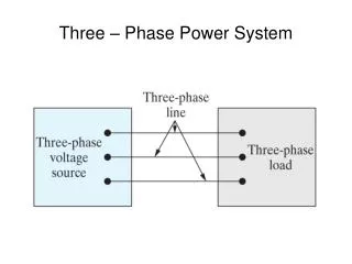
Three phase system. d. Flux density B [T]. l. . L. M. N. A. . Single phase generator. Current induces in the coil as the coil moves in the magnetic field. Generator for single phase. Note

E N D
d Flux density B [T] l L M N A Single phase generator Current induces in the coil as the coil moves in the magnetic field Generator for single phase Note Induction motor cannot start by itself. This problem is solved by introducing three phase system Current produced at terminal
Three phase generator Instead of using one coil only , three coils are used arranged in one axis with orientation of 120o each other. The coils are R-R1 , Y-Y1 and B-B1. The phases are measured in this sequence R-Y-B. I.e Y lags R by 120o , B lags Y by 120o.
The three winding can be represented by the above circuit. In this case we have six wires.The emf are represented by eR , eY, eB.
The circuit can be simplified as follows, where R1 can be connected to Y and Y1 can be connected to B. In this case the circuit is reduced to 4 wires. Since the total emf is zero, R and B1 can be connected together, thus we arrive with delta connection system.
Delta connection of three phase windings Fig. B Fig.A Fig. C • Since the total emf is zero, R and B1 can be connected together as in Fig.A , thus we arrive with delta connection system as in Fig. C. • The direction of the emf can be referred to the emf waveform as in Fig. B where PL is +ve (R1-R), PM is –ve (Y-Y1) and PN is –ve (B-B1).
M Star connection of three phase windings • R1, Y1 and B1 are connected together. • As the e.m.f generated are assumed in positive direction , therefore the current directions are also considered as flowing in the positive direction. • The current in the common wire (MN) is equal to the sum of the generated currents. i.e iR+iY+iB . • This arrangement is called four –wire star-connected system. The point N refers to star point or neutral point.
Three-wire star-connected system with balanced load For balanced loads, the fourth wire carries no current , so it can be dispensed
Instantaneous currents’ waveform for iR, iY and iB in a balanced three-phase system.
-VY VB VRY VBR VR -VR -VB VY VYB Voltage and current in star connection • VRY, VYB and VBR are called line voltage • VR, VY and VB are called phase voltage From Kirchoff voltage law we have In phasor diagram
-VY VB VRY VBR VR -VR -VB VY VYB For balanced load VR , VY and VB are equaled but out of phase VRY = VL30; VYB = VL-90; VBR = VL150; VR = VP30; VY = VP-90; VB = VP150; therefore
then and
IR I1 -I3 -I2 IB I3 I2 -I1 IY Voltage and current in Delta connection • IR, IY and IB are called line current • I1, I2 and I3 are called phase current From Kirchoff current law we have VP VL In phasor diagram
IR I1 -I3 -I2 IB I3 I2 -I1 IY Since the loads are balanced, the magnitude of currents are equaled but 120o out of phase. i.e I1 =I2=I3 ,=IP Therefore:- I1 = VP30; I2 = VP-90; I3 = VP150; IR = IL30; IY = IL-90; IB = IL150; Where IP is a phase current and IL is a line current Thus IR=IY=IB = IL
Unbalanced load Example 1 In a three-phase four-wire system the line voltage is 400V and non-inductive loads of 5 kW, 8 kW and 10 kW are connected between the three conductors and the neutral. Calculate: (a) the current in each phase (b) the current in the neutral conductor.
Voltage to neutral Current in 10kW resistor Current in 8kW resistor Current in 5kW resistor
INV IN IR IBH IYH INH IBV IYV IB IY Resolve the current components into horizontal and vertical components.
Example 2 • A delta –connected load is arranged as in Figure below. The supply voltage is 400V at 50Hz. Calculate: • The phase currents; • The line currents. (a) I1 is in phase with VRY since there is only resistor in the branch
-I3 30o In branch between YB , there are two components , R2 and X2 In the branch RB , only capacitor in it , so the XC is -90 out of phase.
(b) q=30o q = 71o 34’ -60o= 11o 34’
Power in three phase Active power per phase = IPVPx power factor Total active power= 3VPIP x power factor If IL and VL are rms values for line current and line voltage respectively. Then for delta () connection: VP = VL and IP = IL/3. therefore: For star connection () : VP = VL/3 and IP = IL. therefore:
Example 3 • A three-phase motor operating off a 400V system is developing 20kW at an efficiency of 0.87 p.u and a power factor of 0.82. Calculate: • The line current; • The phase current if the windings are delta-connected. (a) Since And line current =IL=40.0A (b) For a delta-connected winding
Example 4 Three identical coils, each having a resistance of 20 and an inductance of 0.5 H connected in (a) star and (b) delta to a three phase supply of 400 V; 50 Hz. Calculate the current and the total power absorbed by both method of connections. First of all calculating the impedance of the coils where
Star-connection Since it is a balanced load Power absorbed
415 Example 5 A balanced three phase load connected in star, each phase consists of resistance of 100 paralleled with a capacitance of 31.8 F. The load is connected to a three phase supply of 415 V; 50 Hz. Calculate: (a) the line current; (b) the power absorbed; (c) total kVA; (d) power factor .
Admittance of the load where Line current Volt-ampere per phase Active power per phase Total active power
(b) Reactive power per phase Total reactive power Total volt-ampere (c) (d) Power Factor = cos = cos 45 = 0.707 (leading)
Example 6 A three phase star-connected system having a phase voltage of 230V and loads consist of non reactive resistance of 4 , 5 and 6 respectively. Calculate: (a) the current in each phase conductor (b) the current in neutral conductor and (c) total power absorbed.
38.3 A 57.5 A 46 A (b) X-component = 46 cos 30 + 38.3 cos 30 - 57.5 = 15.5 A Y-component = 46 sin 30 - 38.3 sin 30= 3.9 A Therefore (c)