Download
1 / 21
210 likes | 297 Vues
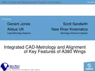
2004 Coordinate Measurement System Committee. Presented by. Integrated CAD-Metrology and Alignment of Key Features of A380 Wings. Introduction – A380 Metrology at Broughton. Measurement Systems Laser Trackers Alignments of kinematic mechanisms Laser Radar Scanner

E N D
2004 Coordinate Measurement System Committee Presented by Integrated CAD-Metrology and Alignment of Key Features of A380 Wings Use menu "View - Header & Footer" for Presentation title - Siglum - Reference
Introduction – A380 Metrology at Broughton • Measurement Systems • Laser Trackers • Alignments of kinematic mechanisms • Laser Radar Scanner • Direct measurement of performance and interface features • Assembly of the Airbus A380 Wing • Build and Inspect directly to features • Integrate Metrology Systems and CAD • Optimize Build and Inspection of Wing Performance Features • Software Platform • Graphical environment and reports • Relationship Fitting optimize part alignment to CAD • Confident product configuration and communication 2004 Coordinate Measurement System Committee
LSM systems used on A380 and why Current systems used on the A380 Project at Airbus Broughton are Laser trackers (7) and a laser radar (1) The laser tracker instrument was procured because:- • It is highly versatile • It’s performance is commensurate with the range of design specifications • It’s ability to track and therefore build The Laser radar was procured because:- • It’s ability to measure in a targetless fashion • It’s ability to mostly automate the data gathering process • It’s ability to measure large amounts of data quickly • It’s performance is commensurate with the range of design specifications 2004 Coordinate Measurement System Committee
Measured features on an A380 Wing set OVERWING PANEL x 2 ENGINE PYLONS x 4 UNDERWING PANEL x 2 FLAP BEAMS x 10 Laser tracker WING ROOT x 2 Laser Radar AILERONS x 6 WING TWIST x 2 FLAP TRACK FAIRINGS X 48 FALSEWORK X 4 SPOILERS x 16 A total of 96 planned measurement tasks per wing set! 60% involve building routines as well as inspection 2004 Coordinate Measurement System Committee
Measured features on an A380 Wing set Engine Pylon Geometry Forks Thrust Spigot Aft fitting Aims: -To inspect the position of the Forks in the X direction -To inspect the position of the Aft fitting in the Y direction -To inspect the orientation of the Forks to the engine thrust line 2004 Coordinate Measurement System Committee
Measured Features on an A380 Wing set Z Y X Wing Tip Falsework Surface B Surface A Aim: To blend profile of surface A into surface B From an initial alignment the relationships function allows a fine adjustment of the translation in Z and rotation around X. 2004 Coordinate Measurement System Committee
Stage 02 Measurement requirement Wing Root Measurement = Datum reference points Top skin profile Front spar Centre spar LR200 Rear spar Bottom skin profile Aims: To measure top and bottom skin surface profiles and to measure spar orientation with respect to the CAD model Junction to Wing box/fuselage 2004 Coordinate Measurement System Committee
Stage 02 Measurement requirement Wing Incidence Incidence Nose up tolerance Incidence primary datum Incidence Nose down tolerance Aim: To understand the extent and sense of rotation of the aerofoil - Wing set as well as asymmetrical tolerance - Incidence is measured via 6 opposing pairs of points per wing =Measured points using hidden point device 2004 Coordinate Measurement System Committee
Future metrology software requirements at Airbus LEAST SQUARES FITTING EASIER AND POSITIVE SCRIPTING OPTIONS & OUTCOMES ATTRIBUTEYEYES/NO SOLUTION REQUIRED SKILLFULL OPERATORS REQUIRED HINGE LINE FITTING TODAY HINGE LINE FITTING OPTIMISED ELECTRONIC GAUGING = MULTIPLE SOLUTIONS FITTING RESIDUALS STORED FOR LATER USE ELECTRONIC GAUGING SOLUTION 2004 Coordinate Measurement System Committee
Measurement Control • Measurement Control with CAD Model Driven Assembly • Build/Inspect direct to model definition produces common results Minimal secondary support tooling (e.g. Shop Aids and Targeting) • Model controls conformance • Tolerances are relative to features • Pragmatic GD&T with feature to feature relationships • Quality Procedures • Graphical Reports improves communication • SPC Charting yields process control • Unified Spatial Metrology Network to ensure process capabilities • Feature based alignment strategies • Relationship Fitting direct alignment of measurements and instruments to model 2004 Coordinate Measurement System Committee
Model Driven Verification with Integrated Metrology Automated inspection of critical interface features with Laser Scanner 2004 Coordinate Measurement System Committee
Model Driven Assembly Kinematics mechanism alignment directly to CAD 2004 Coordinate Measurement System Committee
Hinge Line Alignment Reporting Working Frame Bull's-eye Charts Showing Hinge Line Tolerances and Results 2004 Coordinate Measurement System Committee
Integrating Measurement Technologies - USMN • USMN – Network Optimization • Determine real-world uncertainty fields for Points and Features • Characterize actual instrument uncertainty performance from Shop Floor Surveys • Take advantage of relative uncertainty of measurement components • Multiple Instrument Network Scanner + Tracker • Systems operate synchronously in a cooperative network aligned with USMN • USMN orientation produces optimal results • Traceable uncertainty estimates for Points, Instruments, and Features • Manage Measurement Uncertainties – Confidence • Graphical Reports Communicate Process Improvements • Geometric fitting uncertainty (sphere, line, plane, cylinder, etc) 2004 Coordinate Measurement System Committee
Metrology Confidence with USMN on Wing Survey 95.46% Confidence Interval (2-sigma) 2004 Coordinate Measurement System Committee
Hinge Line Targeting Uncertainty Extrapolation Pt Targeting Expands Uncertainty Uncertainty Expanded by 23% 2004 Coordinate Measurement System Committee
Hinge Line Targeting Uncertainty Mid Pt Targeting Reduces Uncertainty Uncertainty Reduced by 16% 2004 Coordinate Measurement System Committee
Relationship Fitting Methodology • Align critical features within the A380 wing system: • Model interdependence • Relative importance with weighting • Interaction between key kinematic mechanisms and critical interface features • Each relationship has an inherent local reporting frame • Best-Fit Weighted Relationships • As-Built configuration is optimized to its nominal CAD model on the shop floor • Simultaneously fits the constraints defined by the relationships • Relative importance of each constraint is controlled using weights set by the production team 2004 Coordinate Measurement System Committee
Relationship Fitting: Interface Feature Alignment Scanner Survey Optimized to CAD 2004 Coordinate Measurement System Committee
Relationship Fitting: Hinge Line Kinematics Optimize Hinge Line Configuration + Build to Nominal 2004 Coordinate Measurement System Committee
Q & A session 2004 Coordinate Measurement System Committee