Download
1 / 31
320 likes | 326 Vues
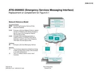
Review of Networking Concepts Part 2: Protocols and Services. Layered Protocol Architectures Network Services OSI Reference Model. Summary of Topics. Protocol, Layers, Encapsulation Services Protocol Architecture OSI Reference Model. Communications Architecture.

E N D
Review of Networking ConceptsPart 2: Protocols and Services Layered Protocol Architectures Network Services OSI Reference Model CS757
Summary of Topics • Protocol, Layers, Encapsulation • Services • Protocol Architecture • OSI Reference Model CS757
Communications Architecture • Protocols are a set of rules and conventions. By enforcing that communicating parties adhere to a common protocol, communication is made possible • The complexity of the communication task is reduced by breaking it up in several layers of smaller tasks: • Each layer is responsible for a specific subtask • Each layer has its own protocols • A structured set of layered protocols is called a layeredcommunicationsarchitectureorprotocol suite CS757
Layered Network Architecture • In a Layered Network Architecture, the services are grouped in a hierarchy of layers • Layer N uses services of layer N-1 • Layer N provides services to layer N+1 • Example: Network Architecture CS757
Layered Communications • A communication layer is completely defined by (a) A peer protocol which specifies how entities at layer-N communicate (b) The service interface which specifies how adjacent layers at the same system communicate • Note: When talking about two adjacent layers, (a) the higher layer is a service user, and (b) the lower layer is a service provider CS757
Layered Communications • Important: • The communication between entities at the same layer is logical • The physical flow of data is vertical CS757
Logical flow of information Example: Sending a Letter • Bob sends a letter to Alice Bob Alice Bob’s mailbox Alice’smailbox Postman CS757
N+1 Layer Peer Protocol Request Delivery IndicateDelivery Service Primitives Communication services are invoked via function calls. The functions are called service primitives N+1 LayerEntity N+1 LayerEntity N LayerEntity N LayerEntity CS757
N+1 Layer Peer Protocol Request Delivery IndicateDelivery Service Primitives Recall: A layer N+1 entity sees the lower layers only as a service provider N+1 LayerEntity N+1 LayerEntity Service Provider CS757
Service Access Points • A service user accesses services of the service provider at Service Access Points (SAPs) • A SAP has an address that uniquely identifies where the service can be accessed CS757
Exchange of Data • Assume a layer-N entity at A wants to send data to a layer-N peer entity to B • The unit of data send between peer entities is called a Protocol Data Unit (PDU) • For now, let us think of a PDU as a single packet • What actually happens: Layer N passes the PDU to one of A’s SAPs at layer N-1 • The layer N-1 entity (at A) then constructs its own PDU which it sends to the layer N-1 entity at B • Note: PDU at layer N-1 = Header +PDU at layer N A B CS757
Exchange of Data A B CS757
Data Data 4 Data 4 3 Data 4 3 2 Data Data 4 4 3 3 2 2 1 1 Layering and Encapsulation • At the sending site, each layer adds a header to the PDU (encapsulates) from the higher layer Application Application Layer 4 Layer 4 Layer 3 Layer 3 Layer 2 Layer 2 Layer 1 Layer 1 CS757
Data Data 4 Data 4 3 Data 4 3 2 Data 4 3 2 1 Layering and Encapsulation • At the receiving site, the headers are removed by the corresponding layers Application Application Layer 4 Layer 4 Layer 3 Layer 3 Layer 2 Layer 2 Layer 1 Layer 1 CS757
Protocol Architectures • The following protocol architectures are relevant today: • OSI Reference Model • Defined as a big effort in the 1970’s by ISO to specify a comprehensive set of protocols for networking. • The effort failed, in that the defined protocols are not widely used. However, the concepts and terminology defined in the OSI model are the lingua franca of many networkers • TCP/IP Protocols Suite • The Internet protocol architecture is not the result of a design effort, but has evolved over several decades • ATM Protocol Stack • An example that protocols can be designed by a committee. Future relevance will depend on the success of ATM CS757
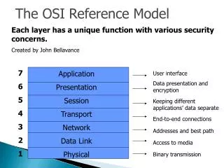
OSI Reference Model • In 1977 the International Standardization Organization (ISO) developed a model for a layered network architecture • This effort was completed in 1983 and is known as the Open Systems Interconnection (OSI) Reference Model • The OSI model defines seven layers: Layer 7: Application Layer Layer 6: Presentation Layer Layer 5: Session Layer Layer 4: Transport Layer Layer 3: Network Layer Layer 2: Data Link Layer Layer 1: Physical Layer (Layer 0: Interconnection Media) CS757
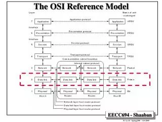
OSI Layers CS757
OSI Model in a Switched Communication Network • Only end systems have all layers • Nodes only have the lower 3 layers CS757
Physical Layer (Layer 1) Service:Transmission of a raw bit stream over a communication channel Functions: Conversion of bits into electrical or optical signals Examples: X.21, RS-232-C CS757
Data Link Layer (Layer 2) Service: Transfer of frames over a single link Functions: synchronization, error control, flow control Examples: PPP, SLIP, HDLC, CCITT LAP-D frame frame CS757
Network Layer (Layer 3) Service: End-to-end delivery of packets Functions: Routing, Addressing, Switching, Congestion Control. Examples: IP, X.25, CLNP packet CS757
Transport Layer (Layer 4) Service: Delivery of data between end systems. Functions: Connection establishment/management/termination, Error Control, Flow Control, Multiplexing. Examples: TCP, UDP, ISO TP0 - TP4. data data CS757
“Higher Layers” of the OSI Reference Model • Session Layer (Layer 5): Service: Support the dialog between cooperating application programs Functions: Session establishment/management/termination, Synchronization, Recovery Examples: ISO session protocol, RPC • Presentation Layer (Layer 6): Service: Provides freedom from compatibility problems Functions: Virtual device support, syntax conversion, encryption Examples: ISO presentation protocol • Application Layer (Layer 7): Service: Provides network access to application programs Functions: Everything is application specific Examples: File Transfer, Electronic Mail CS757
The TCP/IP protocol suite is the protocol architecture of the Internet The TCP/IP suite has four layers: Application, Transport, Network, and Data Link Layer End systems (hosts) implement all four layers. Gateways (Routers) only have the bottom two layers. TCP/IP Protocol Suite CS757
Functions of the Layers • Data Link Layer: • Service: Reliable transfer of frames over a link Media Access Control on a LAN • Functions: Framing, media access control, error checking • Network Layer: • Service: Move packets from source host to destination host • Functions: Routing, addressing • Transport Layer: • Service: Delivery of data between hosts • Functions: Connection establishment/termination, error control, flow control • Application Layer: • Service: Application specific (delivery of email, retrieval of HTML documents, reliable transfer of file) • Functions: Application specific CS757
TCP/IP Suite and OSI Reference Model The TCP/IP protocol stack does not define the lower layers of a complete protocol stack CS757
The B-ISDN ATM Reference Model • ATM technology has its own protocol architecture Control Plane User Plane Upper Layer Upper Layer End-to-end layer ATM Adaptation Layer (AAL) Transfer of Cells ATM Layer Same as in OSI Physical Layer CS757
Layers of ATM Host A ATM Switch Host B CS757
ATM Layer • The ATM Layer is responsible for the transport of 53 cells across an ATM network • The ATM Layer can provide a variety of services for cells from an ATM virtual connection: • Constant Bit Rate (CBR) • guarantees a fixed capacity, similar to circuit switching • guarantees a maximum delay for cells • Variable Bit Rate (VBR) • guarantees an average throughput • can guarantee maximum delay • Available Bit Rate (ABR) • guarantees ‘fairness” with respect to other traffic • Unspecified Bit Rate (UBR) • service is on a “best effort” basis CS757