Download
1 / 59
590 likes | 990 Vues
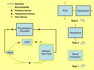
LVAD System Review. System Overview. Smiha Sayal. System Overview. Left Ventricular Assist Device (LVAD) Mechanical device that helps pump blood from the heart to the rest of the body. Implanted in patients with heart diseases or poor heart function. System Goal.

E N D
System Overview Smiha Sayal
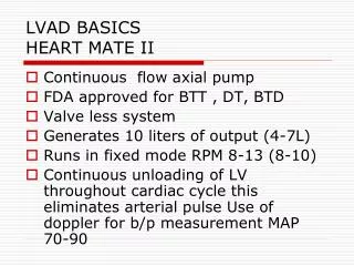
System Overview • Left Ventricular Assist Device (LVAD) • Mechanical device that helps pump blood from the heart to the rest of the body. • Implanted in patients with heart diseases or poor heart function.
System Goal • Miniaturize the existing LVAD system to achieve portability while retaining its safety and reliability.
Original System • “Black box” architecture used during development • Large, not portable • Runs on AC power
P10021’s System • Has both internal / external components • Equivalent to our “Option 2” • Unfinished implementation
Customer Needs • Safe • Robust • Affordable • Easy to wear and use • Interactive with user • Controllable by skilled technician • Comparable performance • Compatible with existing pump
Other LVAD Technologies CorAide (NASA)
Concepts: Option 1 All electronics external
Concepts: Option 2 ADC internal only
Concepts: Option 3 Pump and motor control internal
Concepts: Option 4 All electronics and battery internal
Concepts: Option 5 All electronics and battery internal
Concept Generation Highlights Best Option 350 273 200 153 • Option 5 • Relatively small internal volume • Slightly higher risk of internal • failure • Minimum 249
Enclosure Design Nicole Varble and Jason Walzer
External Enclosure • Needs • The external package should be lightweight/ robust/ water resistant • The devices should be competitive with current devices • The device should fit into a small pouch and be comfortable for user and be comfortable for the user • The external package should resist minor splashing • The device should survive a fall from the hip • Risks • Housing for the electronics is too heavy/large/uncomfortable • Water can enter the external package and harm the electronics • The housing fails before the electronic components in drop tests • The electronic components can not survive multiple drop tests
Rapid Prototyping http://www.dimensionprinting.com/ • Machinable • Material can be drilled and tapped (carefully) • Accepts CAD drawings • Complex geometries can be created easily • Ideal for proposed ergonomic shape • Builds with support layer • Models can be built with working/moving hinges without having to worry about pins • Capable of building thin geometries • ABSplus • Industrial thermoplastic • Lightweight - Specific gravity of 1.04 • Porous • Does not address water resistant need
ABS Plastic • Important Notes • Relatively high tensile strength • Glass Transition well above body temperature • Specific Gravity indicates lightweight material
Feasibility- Water Ingress Test Loctite Spray on Rubberized Coating • Need: The external package should resist minor splashing • Specification: Water Ingress Tests • Once model is constructed, (user interface, connectors sealed, lid in place) exclude internal electronics and perform test • Monitor flow rate (length of time and volume) of water • Asses the quality to which water is prevented from entering case by examining water soluble paper • Risk: Water can enter the external package and harm the electronics • Preventative measures: • Spray on Rubber Coating or adhesive • O-rings around each screw well and around the lid • Loctite at connectors • Preliminary Tests without protective coating show no traceable water ingress
Feasibility- Robustness Testing • Need: The device should survive a fall from the hip • Specification: Drop Test • Drop external housing 3 times from 1.5 m, device should remain fully intact • Specify and build internal electrical components • Identify the “most vulnerable” electrical component(s) which may be susceptible to breaking upon a drop • Mimic those components using comparable (but inexpensive and replaceable) electrical components, solder on point to point soldering board • Goal • Show the housing will not fail • Show electronics package will not fail, when subjected to multiple drop tests • Risks • The housing fails before the electronic components in drop tests (proved unlikely with prototype enclosure) • The electronic components can not survive multiple drop tests • Preventative Measures • Eliminate snap hinges from housing (tested and failed) • Test the housing first • Design a compact electronics package
Feasibility- Heat Dissipation of Internal Components Tout Tin h Q t, k 130°C is absolute maximum for chip junction temperature in order to function properly Goal- comfort for the user Assumed steady state, heat only dissipated through 3 external surfaces Maximum heat dissipation ~25W Actual heat dissipation ~5W
Prototype Enclosure • Survived drop test • Water resistant • Plastic is machinable • Drilled, tapped, milled • Helicoils should be used to tap holes • Constant opening and screwing and unscrewing of lid will result in stripped threads • Approximate wall thickness (6mm) • Distance between center of holes and wall needs to be increased • Some cracking occued • Latches are not feasible
User Interface From Pump To Battery BATTERY MENU + Speed Battery Life Fault Indication To Battery To/From Computer ERROR OK - Components: Indication of battery life (3x LED) Indication of Fault (LED and Buzzer) Indication of levitation (LED) Display Increase/Decrease Speed (2x Button) Menu (Button) Connectors: 26- pin LEMO connector USB connector Battery Terminals (x2) OK: Indication of levitation ERROR: No Levitation, connection errors
User Interface- Components LED Backlit display with waterproof bezel and o-ring G/R/Y LEDs with O-ring and waterproof bezel Waterproof buttons with O-ring
User Interface- Connectors Current Model: Part # EGG 2K 326 CLL Proposed: Part # EEG 2K 326 CLV Pin Layout
Embedded Control System Andrew Hoag and Zack Shivers
Control System • Requirements • Selecting suitable embedded control system • Designing port of control logic to embedded system architecture • Customer Needs • Device is compatible with current LVAD • Device is portable/small • Allows debug access
Impeller Levitation • Impeller must be levitating or “floating” • Electromagnets control force exerted on impeller • Keeps impeller stabilized in the center • Position error measured by Hall Effect sensors
Levitation Algorithm • Algorithm complexity influences microcontroller choice • Electronics choices affect volume / weight • Proportional – Integral – Derivative (PID) • Very common, low complexity control scheme http://en.wikipedia.org/wiki/PID_controller
Embedded System Selection • Requirements: • Can handle PID calculations • Has at least 8x 12-bit ADC for sensors at 2000 samples/sec • Multiple PWM outputs to motor controller(s) • Same control logic as current LVAD system • Reprogrammable
Embedded System Selection • Custom Embedded • dsPIC Microcontroller • Blocks for Simulink • Small • Inexpensive (<$10 a piece) • TI MSP430 • Inexpensive (<$8 a piece) • Small, low power • COTS Embedded • National Instruments Embedded • Uses LabVIEW • Manufacturer of current test and data acquisition system in “Big Black Box” • Large to very large • Very expensive (>$2000)
Control Logic/Software • Closed-loop feedback control using PID – currently modeled in Simulink for use with the in “Big Black Box” • Additional microcontroller-specific software will be required to configure and use A/D, interrupts, timers.
Life Critical System • Not at subsystem level detail yet. • Life-critical operations would run on main microcontroller. • User-interface operations run on separate microcontroller. • Possible LRU (Least Replaceable Unit) scheme
Technician/Field Software Debug Interface • USB • USB is everywhere. • Requires custom PC-side software. • Requires processor support. • Serial (RS-232) • Many computers don’t have serial ports anymore. • Can use $15 COTS USB to Serial adapter. • Can use COTS terminal tools.
Technician/Field Software Debug Interface • Example of using COTS tool – Windows HyperTerminal (free/part of Windows)
Microcontroller Search Parameters • A/D • 0-5V • 8x12-bit @5ksps (kilo-samples/sec) • This equates to 40ksps minimum for A/D • PWM • General I/O for UI controls • At least 10x digital • At least 5x analog • UART (for Serial connection)
Microcontroller Packaging • L/TQFP – Low-profile/Thin Quad Flat Pack • Small surface-mount (PCB mount) chip package. • Is solderable (by skilled solderer) • Body thickness up to 1.0mm, sizes range from 5x5mm to 20x20mm
Microcontroller • 2 families of Microcontrollers • dsPIC from Microchip • MSP430 from Texas Instruments
Microchip dsPIC • dsPIC30F5011 (16-bit architecture) • Max CPU speed 30 MIPS (Million Instructions/sec) • 2.5-5.5V operating voltage • 66KB Flash, 4KB RAM, 1KB EEPROM • 16x12-bit ADC @ 200ksps • -40 to 85C operating temp • 64-lead TQFP – body 10x10mm, overall 12x12mm • Cost [1-25 units] = $7.21
TI MSP430 • MSP430F5435A (16-bit architecture) • Max CPU speed 25 MIPS (Million Instructions/sec) • 2.2-3.6V operating voltage • 192KB Flash, 16KB RAM • 16x12-bit ADC @ 200ksps • 3 Timer modules (with total of 15 timer channels) • -40 to 85C operating temp • 80-lead LQFP – body 10x10mm, overall 12x12mm