Download
1 / 8
80 likes | 204 Vues
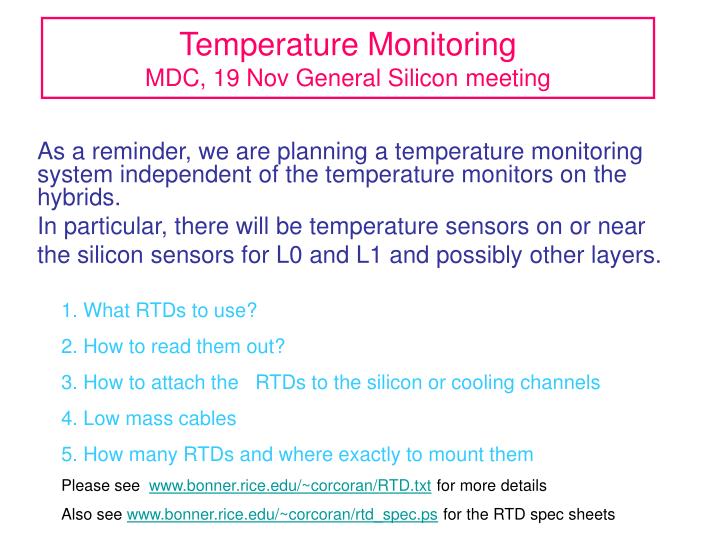
Temperature Monitoring MDC, 19 Nov General Silicon meeting. As a reminder, we are planning a temperature monitoring system independent of the temperature monitors on the hybrids. In particular, there will be temperature sensors on or near

E N D
Temperature MonitoringMDC, 19 Nov General Silicon meeting As a reminder, we are planning a temperature monitoring system independent of the temperature monitors on the hybrids. In particular, there will be temperature sensors on or near the silicon sensors for L0 and L1 and possibly other layers. 1. What RTDs to use? 2. How to read them out? 3. How to attach the RTDs to the silicon or cooling channels 4. Low mass cables 5. How many RTDs and where exactly to mount them Please see www.bonner.rice.edu/~corcoran/RTD.txt for more details Also see www.bonner.rice.edu/~corcoran/rtd_spec.ps for the RTD spec sheets
RTDType The hybrids use a Honeywell surface mount device, 1000Ω Pt thin film RTD. Honeywell has similar devices with 100 Ω resistance. 1000 ohm vs 100 Ω: For the hybrid application, 1000Ω is necessary since they plan a 2-wire readout. For the stand-alone system, we plan a 4-wire readout (which cancels the lead resistance) so 100 Ω device should be fine The readout through the cryo system for 100Ω is more straightforward.
Readout through the D0 Cryo system using standard PCL There are three choices of readout modules: • CTI-7038, 0-2000 ohms, pulsed current • CTI-2557 standard module for 100 ohm RTD, industry standard, 250 microA DC current 3. CTI-2557 SPQ334, special Fermilab version, 0-1000 ohms, 10 microA DC current, would need further modification for 1000 ohm RTD
RTDreadout The CTI 2557 is an off-the-shelf module The CTI 7038 is also off-the-shelf, but the pulsed current is probably not appropriate for use close to the silicon The modified CTI 2557 can be further modified for use with 1000 ohm RTDs at some additional cost—one time $1200 re-engineering fee plus $300 extra per 16-channel module Dan Markley will help us get a test setup at Rice to test the devices and readout.
RTD self heating 100 ohm RTD, 250 micoramps DC current gives 6.25 microwatts of power 1000 ohm RTD, 10 microamps of DC current gives 0.1 microwatts of power Self-heating of these RTDs is given on spec sheet as 0.3mWatts/0C Self-heating should not be an issue, but should be checked. I recommend the 100 ohm RTD with standard CTI2557 readout module.
Low mass cables A mini-ribbon cable from Lakeshore looks reasonable—four conductor, with polyimide insulation. The RTD can be directly soldered to the cable and the leads potted in epoxy. Some samples of RTDs/cables will be sent to Fermilab this week.
Connection to high mass cable Where should the transition from low mass to high mass cables be made? Perhaps there should there be two connections…one in the area of the junction cards, one at the horseshoe. Needs some thought and discussion with engineers and others.
Number and locations of RTDs Under discussion…I plan to visit Seattle sometime in January to discuss this issue for L0/L1. The total number will probably be in the range of 100-150.