Download

1 / 68
690 likes | 853 Vues
Cost-Oriented Design of a 14-bit Current Steering DAC Macrocell. IEEE International Symposium on Circuits and Systems. May 25-28 th , 2003. Janusz A. Starzyk Ohio University. Russell P. Mohn Sarnoff Corporation. Ohio University School of Electrical Engineering and Computer Science.

E N D
Cost-Oriented Design of a 14-bit Current Steering DAC Macrocell IEEE International Symposium on Circuits and Systems May 25-28th, 2003 Janusz A. Starzyk Ohio University Russell P. Mohn Sarnoff Corporation Ohio University School of Electrical Engineering and Computer Science
Outline • Introduction • Statistical Yield Model • Reduction of Systematic Errors • Design Cost Consideration • DAC Implementation • Conclusion and Future Work
Introduction • Design Consideration based On the Statistical Model • Current Source Analysis • Reference Circuit Design and Analysis • Spreading of the Composite Transistors and Random Walk • Thermometer Circuit Design • Glitches and Dynamic Performance • Architectures and Layout • Top Level Simulation Results • Estimated Design Performance
Organization • The DNL and INL Specifications • Design Consideration based On the Statistical Model • Segmentation of the Composite Transistors and Random Walk • Glitches and Dynamic Performance • Architectures and Layout • Simulation Results • Summary and Estimated Design Performance Figures
DNL standard deviation • for the segmented architecture • B=4, so to meet the requirements for DNL
Segmentation of the Composite Transistors and Random Walk • depends on the transistor area A and spacing D as • where A, AVTand S are process related constants
Segmentation of the Composite Transistors and Random Walk • The random errors are determined by mismatch • The systematic errors are determined by process, temperature, and electrical gradients • In optimally designed DAC the INL and DNL errors depend only on the random errors level • Increasing transistor area reduces the random errors. • The systematic errors are layout-dependent and are minimized by transistor switching scheme.
Random errors - unit transistor requirements • The minimum area of the unit transistor Parameters A and AVT are technology dependent
The Level of Systematic Errors • where k=Acell /A>1 is a current cell layout coefficient with Acell -unit current cell area
Current-source Matching vs. the Design Area for 12 bit DAC Green line indicates the effect of systematic errors
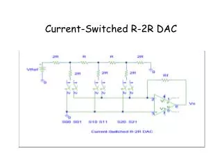
Current Source Analysis uneven output voltage Iout1=13.33mA, Iout2=0 mA, Vout1=1V, Vout2=0 V
dI Ioff Current Source Analysis uneven output voltage In order to achieve satisfactory INL level we must keep the cut-off current low Vd src So the cut-off current is limited by Vd c Vout1 Vout2 Io
Current Source Analysis even output voltage Iout1=Iout2=6.66 mA, Vout1=Vout2=0.5V
Reference Resistor and Output Current The following empirical relation holds for Iout<20mA
Layout specifications of the 12-bit DAC • DAC is built as a segmented architecture with 8-bit thermometer and 4-bit binary sections (to lower the glitches) • LSB cell area (1/4 of unary source cell) is A=308 m2 with W=17 m and L=18 m • 8-bit thermometer decoder is designed in two groups- one with 3 thermometer bits and second with 5 bits (MSBs) • Random walk is implemented with derived permutation sequence to minimize systematic errors • Symmetrical layout, synchronization of control signals, synchronization of unary and binary current source transistor switching, and the cascode structure of the unit current sources control dynamic performance.
Spreading of the Composite Transistors and Random Walk • The random errors are determined by mismatch • The systematic errors are determined by process, temperature, and electrical gradients • In optimally designed DAC the INL and DNL errors depend only on the random errors level • Increasing transistor area reduces the random errors. • The systematic errors are layout-dependent and are minimized by transistor switching scheme.
Reduction of Linear Systematic Errors • To compensate for linear errors a symmetrical splitting is required • Each transistor will be split into 4 locations
Wiring - via Placementin Current Sources Current sources are connected to horizontal wires sequentially
Layout • Signal S2(32) • Large capacitive load • Connects 4 symmetrically spread current sources • Unary current source 256 turned OFF
Layout • Signals S2(32) and S2(33) • Current sources controlled by S2(33) are far away from those controlled by S2(32) • Switching sequence designed to minimize systematic errors
Layout • Signals S2(32), S2(33), and S2(34)
Glitches • The glitch current • where Agl is the glitch amplitude, tgl is the glitch period, and t0 is the synchronization mismatch (delay time)
Dynamic Performance • For dynamic performance of DAC due to glitches and parasitic effects the following are recommended: • synchronize the control signals of the switching transistors; • reduce the voltage fluctuation on the drains of the current sources during switching • carefully switch the current source transistor on/off • reduce coupling of the control signals through lowering the voltage of the power supply of the latches. • increase the output resistance in high frequency applications
Dynamic Performance • The synchronization is achieved by equalizing each latch output load capacitance. • Using a large channel length unit current source transistor and tuning the crossing point of the switching control signals such that both switches are never switched off at the same time solves voltage fluctuation at the drain problem • Using an additional cascode transistor increases output impedance for high frequency applications • This architecture has an additional advantage of lowering glitch energy due to the drain voltage variations of the unit source.
Layout • 1 column (8 rows) of latches • Vertical green wires: • Latch input from D flip-flops • Latch output to current source array • Equal load
Layout • Equalizing capacitive load between binary latches and unary latches • Load determined by total length of wires to unary current sources Binary wire Unary wire
2^12 Ramp INL & DNL • Unbalanced capacitive unary and binary loads • INL(2^12) < 10*INL(2^7) • 17 days simulation versus 8 hours simulation