Download
1 / 19
190 likes | 291 Vues
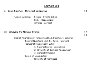
Lecture 1. Course Overview System modeling, analysis and design Basic Circuit Parameters Passive Sign Convention Related educational module: Section 1.1. Pre-requisite and Co-requisite requirements. Pre-requisites (recommended) Basic exposure to electricity and magnetism

E N D
Lecture 1 Course Overview System modeling, analysis and design Basic Circuit Parameters Passive Sign Convention Related educational module: Section 1.1
Pre-requisite and Co-requisite requirements • Pre-requisites (recommended) • Basic exposure to electricity and magnetism • Two semesters of Calculus • Co-requisites (recommended) • Differential equations • Pre- and Co-requisite requirements are rather weak • Superficial introductions to necessary topics provided at the appropriate points during this course
Course Goals • Introduction to modeling, analysis and design of electrical circuits • We will often use a systems-level approach:
What are modeling, analysis and design? • We model the system by determining the mathematical relationship between the input and the output • System analysis often refers to determining the output from a system, for some given input • System design involves creating a system to provide some desired output
Circuits I modeling approach • We will restrict our attention to lumped parameter models of linear, time-invariant systems • Governing equations will be linear, constant-coefficient, ordinary differential equations
Slinky demo • Linear • Nonlinear • Lumped • Distributed
Basic Circuit Parameters • Charge (q) is the basic quantity in circuit analysis • Units are Coulombs (C) 1 Coulomb -6.241018 electrons • Current (i) is the rate of change of charge with time: • Units are Amperes (A)
Basic Circuit Parameters – continued • Voltage (v) is the change in energy of a unit charge at two different points: • Units are Volts (V)
Basic Circuit Parameters – continued • Power (P) is the time rate of change of energy: • Units are Watts (W)
Passive Circuit Elements • For a passive circuit element, the total energy delivered to the circuit element by the rest of the circuit is non-negative • The element can store energy, but it cannot create energy • Active circuit elements can supply energy to the circuit from external sources
Passive Sign Convention • We will assume the sign of the current relative to voltage for passive circuit elements • Positive current enters the node at the higher voltage • Sign must be known for active circuit elements
Passive Sign Convention – continued • You can assume (arbitrarily) either the voltage polarity or the current direction • This assumption dictates the assumed direction of the other parameter • These assumptions provide reference voltage polarities and current directions • Subsequent analysis is performed based on this assumption; a negative result simply means that the assumed voltage polarity or current direction was incorrect
Passive Sign Convention – Example 1 • Provide the appropriate sign convention for the missing parameter on the passive elements represented by grey boxes.
Passive Sign Conventions – Hints • It is generally counter-productive to attempt to determine the “correct” voltage polarities and current directions before analyzing the circuit • Just arbitrarily choose either the assumed voltage polarity or current direction for each passive circuit element • This choice dictates the sign of the other parameter • Perform analysis using assumed signs • Negative signs mean that the assumption was incorrect
Passive Sign Convention – Example 2 • Assign reference voltage and current directions for the passive elements represented by shaded boxes in the circuit below:
Passive Sign Convention – Example 3 • Assign reference voltage and current directions for the passive elements represented by shaded boxes in the circuit below:
Passive Sign Convention – Example 4 • For the circuit below, the sign convention shown is chosen • After analyzing the circuit, it is determined that I1 = -3mA, I2 = 3mA, V1 = -1.5V, and V2 = 2.5V. Re-draw the circuit showing the actual voltages and currents and their directions