Download
1 / 17
170 likes | 284 Vues
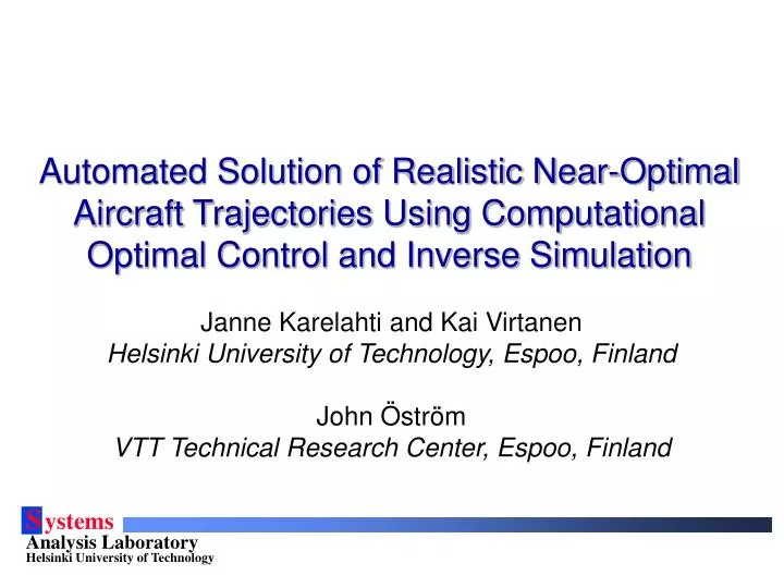
Automated Solution of Realistic Near-Optimal Aircraft Trajectories Using Computational Optimal Control and Inverse Simulation. Janne Karelahti and Kai Virtanen Helsinki University of Technology, Espoo, Finland John Öström VTT Technical Research Center, Espoo, Finland. The problem.

E N D
Automated Solution of Realistic Near-Optimal Aircraft Trajectories Using Computational Optimal Control and Inverse Simulation Janne Karelahti and Kai Virtanen Helsinki University of Technology, Espoo, Finland John Öström VTT Technical Research Center, Espoo, Finland
The problem • How to compute realistic a/c trajectories? • Optimal trajectories for various missions • Minimum time problems, missile avoidance, ... • Trajectories should be flyable by a real aircraft • Rotational motion must be considered as well • Solution process should be user-oriented • Suitable for aircraft engineers and fighter pilots Computationally infeasible for sophisticated a/c models Appropriate vehicle models? No prerequisites about underlying mathematical methodologies
Automatedapproach Solve a realistic near-optimal trajectory 1. Define the problem 2. Coarse a/c model 8. Compute initial iterate Adjust solver parameters 3. No Compute optimal trajectory 4. Sufficiently similar? 7. Delicate a/c model Inverse simulate optimal trajectory 5. Yes Evaluate the trajectories 6. 9. Realistic near-optimal trajectory
2. Define the problem • Mission: performance measure of the a/c • Aircraft minimum time problems • Missile avoidance problems • State equations: a/c & missile • Control and path constraints • Boundary conditions • Vehicle parameters: lift, drag, thrust, ... Angular rate and acceleration, Load factor, Dynamic pressure, Stalling, Altitude, ...
3. Compute initial iterate • 3-DOF models, constrained a/c rotational kinematics • Receding horizon control based method • a/c chooses controls at • Truncated planning horizon T << t*f – t0 • Setk = 0. Set the initial conditions. • Solve the optimal controls over [tk, tk + T] with direct shooting. • Update the state of the system using the optimal control at tk. • If the target has been reached, stop. • Setk = k + 1 and go to step 2.
Direct shooting • Discretize the time domain over the planning horizon T • Approximate the state equations by a discretization scheme • Evaluate the control and path constraints at discrete instants • Optimize the performance measure directly subject to the constraints using a nonlinear programming solver (SNOPT) xN ... x3 x1 Evaluated by a numerical integration scheme ... t3 u3 t4 u4 tN uN t2 u2 t1 u1 T
4. Compute optimal trajectory • 3-DOF models, constrained a/c rotational kinematics • Direct multiple shooting method (with SQP) • Discretization mesh follows from the RHC scheme xN-2 x2 x1 Defect constraints ... t2 u2 t3 u3 t1 u1 t0 u0 tN-1 uN-1 tN=tf uN
5. Inverse simulate optimal trajectory • 5-DOF a/c performance model • Find controls u that produce the desired output history xD • Desired output variables: velocity, load factor, bank angle • Integration inverse method • At tk+1, we have • Solution by Newton’s method: • Define an error function • Update scheme • With a good initial guess, Matrix of scale weights Jacobian
6. Evaluation of trajectories • Compare optimal and inverse simulated trajectories • Visual analysis, average and maximum abs. errors • Special attention to velocity, load factor, and bank angle • If the trajectories are not sufficiently similar, then • Adjust parameters affecting the solutions and recompute • In the optimization, these parameters include • Angular acceleration bounds, RHC step size, horizon length • In the inverse simulation, these parameters include • Velocity, load factor, and bank angle scale weights
Example implementation: Ace • MATLAB GUI: three panels for carrying out the process • Optimization + Inverse simulation: Fortran programs • Available missions • Minimum time climb • Minimum time flight • Capture time • Closing velocity • Miss distance • Missile’s gimbal angle • Missile’s tracking rate • Missile’s control effort • Vehicle models: parameters stored in separate type files • Analysis of solutions via graphs and 3-D animation Missile vs. a/c pursuit-evasion Missile’s guidance laws: Pure pursuit, Command to Line-of-Sight, Proportional Navigation (True, Pure, Ideal, Augmented)
Ace software General data panel a/c lift coefficient profile 3-D animation
Numerical example • Minimum time climb problem, Dt= 1 s • Boundary conditions
Numerical example • Case g0=0 deg • Inv. simulated: Mach vs. altitude plot
Numerical example • Case g0=0 deg, average and maximum abs. errors Velocity histories Load factor histories
Numerical example • Make the optimal trajectory easier to attain • Reduce RHC step size to Dt= 0.15 s • Correct the lag in the altitude by increasing Wn= 1.0 • h(tf)=9971,5 m, v(tf)=400 m/s
Numerical example • Case g0=0 deg, average and maximum abs. errors Velocity histories Load factor histories
Conclusion • The results underpin the feasibility of the approach • Often, acceptable solutions obtained with the default settings • Unsatisfactory solutions can be improved to acceptable ones • 3-DOF and 5-DOF performance models are suitable choices • Evaluation phase provides information for adjusting parameters • Ace can be applied as an analysis tool or for education • Aircraft engineers are able to use Ace after a short introduction