Download
1 / 34
340 likes | 456 Vues
THE DESIGN OF THE AGS-BASED PROTON DRIVER FOR NEUTRINO FACTORY. W.T. WENG, BNL FFAG WORKSHOP JULY 7-11, 2003 KEK, JAPAN. OUTLINES 1. Introduction 2. Performance Challenges 3. Superconducting Linac 4. 1 MW AGS upgrade 5. Ways to 4 MW 6. Possible Application of FFAG.

E N D
THE DESIGN OF THE AGS-BASED PROTON DRIVER FOR NEUTRINO FACTORY W.T. WENG, BNLFFAG WORKSHOPJULY 7-11, 2003KEK, JAPAN
OUTLINES1. Introduction2. Performance Challenges3. Superconducting Linac4. 1 MW AGS upgrade5. Ways to 4 MW6. Possible Application of FFAG
REQUIREMENT FOR A PROTON DRIVER1. Energy 20 to 50 GeV2. Power ~ 4 MW3. Proton ~ 10 x 1021 ppy (107 sec)4. Muon ~ 5 x 10²¹ mpy (107 sec) 5. Reliability ~ 85%
PERFORMANCE CHALLENGES a. Space Charge Effect b. Coherent Instabilities c. Injection and Extraction d. Beam Loss and Collimation e. Target and Horn f. Reliability
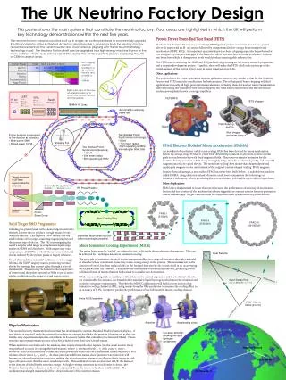
BRAHMS & PP2PP (p) PHENIX (p) STAR (p) AGS/RHIC Accelerator Complex 12:00 o’clock PHOBOS 2:00 o’clock 10:00 o’clock RHIC 8:00 o’clock 4:00 o’clock 6:00 o’clock AGS: Intensity: 7 1013 protons/pulse Injector to RHIC: < 2 hours about every 10 hours Fast extraction U-line High Intensity Source BAF (NASA) m g-2 LINAC HEP/NP Pol. Proton Source AGS BOOSTER Slow extraction TANDEMS
AGS Intensity History 1 MW AGS
1.2 1020 1.0 1020 0.8 1020 Total accelerated protons 0.6 1020 0.4 1020 0.2 1020 0 Total Accelerated Protons at the AGS Slow extracted beam (Kaon decay) Fast extracted beam (g-2) Note: Lower total accelerated protons in later years due to much shorter running time
AGS Upgrade for Neutrino Factory A. 1.2 GeV Superconducting Linac B. AGS Upgrade to 1 MW: Beam loss considerations 1.2 GeV Superconducting Linac 2.5 Hz AGS power supply and rf system Neutrino beam production C. AGS upgrade to 4MW
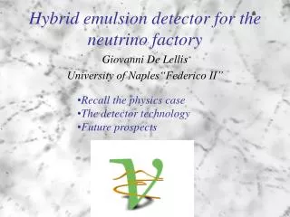
To RHIC To Target Station High Intensity Source plus RFQ 200 MeV Drift Tube Linac BOOSTER AGS 1.2 GeV 28 GeV 0.4 s cycle time (2.5 Hz) 200 MeV 400 MeV Superconducting Linacs 800 MeV 1.2 GeV 0.2 s 0.2 s AGS Upgrade to 1 MW • 1.2 GeV superconducting linac extension for direct injection of ~ 1 1014 protonslow beam loss at injection; high repetition rate possible further upgrade to 1.5 GeV and 2 1014 protons per pulse possible (x 2) • 2.5 Hz AGS repetition ratetriple existing main magnet power supply and magnet current feeds double rf power and accelerating gradient further upgrade to 5 Hz possible (x 2)
Beam Loss at H- Injection Energy AGS Booster PSR LANL SNS 1 MW AGS Beam power, Linac exit, kW 3 80 1000 50 Kinetic Energy, MeV 200 800 1000 1200 Number of Protons NP, 1012 15 31 100 100 Vertical Acceptance A, pmm 89 140 480 55 b2g30.57 4.50 6.75 9.56 NP / (b2g3 A), 1012 / pmm 0.296 0.049 0.031 0.190 Total Beam Losses, % 5 0.3 0.1 3 Total Loss Power, W 150 240 10001440 Circumference, m 202 90 248 807 Loss Power per Meter, W/m 0.8 2.7 4.0 1.8
AGS Injection Simulation • Injection parameters: • Injection turns 360 • Repetition rate 2.5 Hz • Pulse length 1.08 ms • Chopping rate 0.65 • Linac average/peak current 20 / 30 mA • Momentum spread 0.15 % • Inj. beam emittance (95 %) 12 p mm • RF voltage 450 kV • Bunch length 85 ns • Longitudinal emittance1.2 eVs • Momentum spread 0.48 % • Circ. beam emittance (95 %) 100 p mm
New AGS Main Magnet Power Supply presently: • Repetition rate 2.5 Hz 1 Hz • Peak power 110 MW 50 MW • Average power 4 MW 4 MW • Peak current 5 kA 5 kA • Peak total voltage 25 kV 10 kV • Number of power converters / feeds 6 2
Eddy Current Losses in AGS Magnets For 2.5 (5.0) Hz: In pipe: 65 (260) W/m In coil: 225 (900) W/m
AGS RF System Upgrade • Use present cavities with upgraded power supplies (two 300 kW tetrodes/cavity) • presently: • Rf voltage/turn 0.8 MV 0.4 MV • harmonic number 24 6 - 12 • Rf frequency ~ 9 MHz 3 - 4.5 MHz • Rf peak power 2 MW • Rf magnetic field 18 mT
Neutrino Beam Production • 1MW He gas-cooled Carbon-carbon target • New horn design • Target on down-hill slope forlong baseline experiment • Beam dump well above ground water table to avoid activation
Neutrino Spectrum at 1 km Low Z (Carbon) target seemsfeasible for 1 MW, 28 GeV proton beam. Thin low Z target minimizesreabsorption which increases flux of high energy neutrinos
W Beam Line to Homestake Mine Can be directed to any western direction.
Path Towards 4 MW Upgrade I Upgrade II Upgrade III • Linac intensity/pulse 1.0 1014 2.0 1014 2.0 1014 • Linac rep. rate 2.5 Hz 2.5 Hz 5.0 Hz • Linac extraction energy 1.2 GeV 1.5 GeV 1.5 GeV • b2g3 9.6 14.9 14.9 • Beam power 54 kW 144 kW 288 kW • AGS intensity/pulse 0.9 1014 1.8 1014 1.8 1014 • AGS rep. rate 2.5 Hz 2.5 Hz 5.0 Hz • Rf peak power 2 MW 4 MW 8 MW • Rf gap volts/turn 0.8 MV 0.8 MV 1.5 MV • AGS extraction energy 28 GeV 28 GeV 28 GeV • Beam power 1 MW 2 MW 4 MW
4 MW AGS Proton Driver Layout To RHIC To Target Station High Intensity Source plus RFQ 200 MeV Drift Tube Linac BOOSTER AGS 1.2 GeV 28 GeV 0.2 s cycle time (5 Hz) 200 MeV 400 MeV Superconducting Linacs 800 MeV 1.5 GeV 0.1 s 0.1 s
Characteristics of FFAG Accelerator 1. Fixed-field (no ramping), hence good for high repetition rate application. 2. Large momentum acceptance. 3. Limited energy gain, Pf/Pi 3.0. 4. Complicated longitudinal dynamics. 5. High intensity performance has not been demonstrated. 6. Difficulty in injection and extraction.
Possible Application of FFAG 1. Replacement of SCL for AGS Injection. a. electron stripping precludes H- acceleration. b. Need kHz rep. rate for FFAG for multi- batch injection. 2. Energy Doubler for SNS or ISIS is viable. 3. Replace LAR for either SNS or ESS. a. need further work in high intensity acceleration and injection/extraction.
Possible Application of FFAG - Continued 4. May be good for APT. 5. May be good for RIA. 6. Electron Injector (low current, low energy, high rep. rate.
Conclusion An upgraded AGS with 1 MW (further upgradeable to 4 MW) beam power is a cost effective proton driver for a neutrino superbeam for very long baseline experiments and eventually as a proton driver for neutrino factory.